Magnetic sensor, magnetic field sensing method, semagnetic recording head, and magnetic memory device

a magnetic sensor and magnetic field technology, applied in the field of magnetic sensors, can solve the problems of inability to improve the signal-to-noise ratio, the inability to control successfully the heating of the medium and the application of a magnetic field to the medium, and the inability to short circuit the upper and lower ferromagnetic layers, etc., to achieve the effect of reducing or eliminating the transmission signal

Active Publication Date: 2005-10-06
KK TOSHIBA
View PDF6 Cites 159 Cited by
  • Summary
  • Abstract
  • Description
  • Claims
  • Application Information

AI Technical Summary

Problems solved by technology

With this laser-based thermally assisted recording, however, it is difficult to control successfully heating of the medium and application of a magnetic field to the medium.
In addition, the TMR element has a problem that a shot noise component in an output signal is large and hence the S / N ratio (signal-to-noise ratio) cannot be improved.
When the thickness of the tunnel insulating layer is reduced, however, short-circuiting of the upper and lower ferromagnetic layers is liable to occur, lowering the magnetoresistance ratio (MR ratio).
For this reason, it is difficult to fabricate a TMR element which exhibits good characteristics even at high recording densities.
In recent years, magnetic white noise has become a problem in common with the GMR and TMR elements.

Method used


Image

  • Magnetic sensor, magnetic field sensing method, semagnetic recording head, and magnetic memory device
  • Magnetic sensor, magnetic field sensing method, semagnetic recording head, and magnetic memory device
  • Magnetic sensor, magnetic field sensing method, semagnetic recording head, and magnetic memory device

Examples


first embodiment

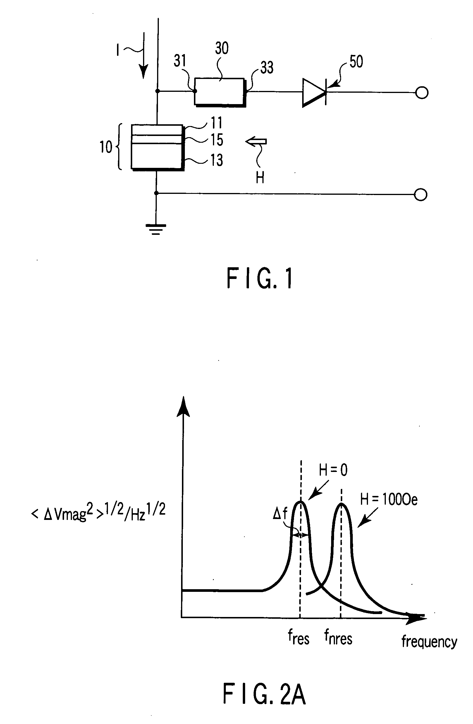
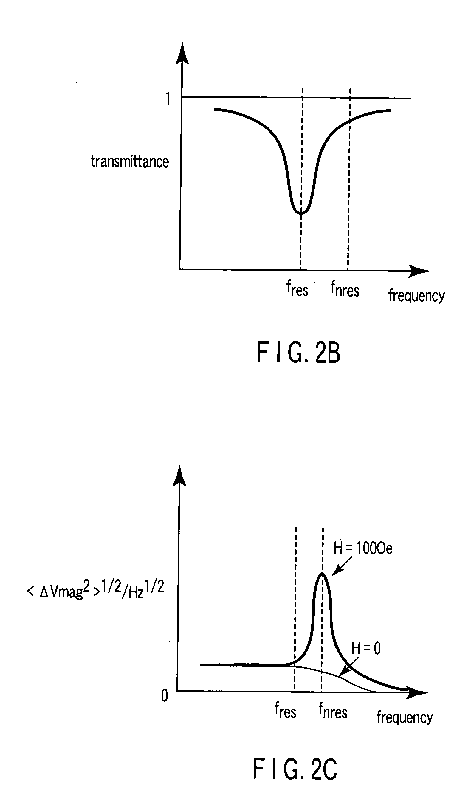
[0047]FIG. 1 shows a circuit diagram of a magnetic sensor according to the first embodiment of the present invention.

[0048] A magnetoresistance element 10 includes a pair of magnetic conductive layers 11 and 13. The magnetic conductive layer 11 is grounded, while the magnetic conductive layer 13 is connected to the input terminal 31 of a microwave filter 30. The output terminal 33 of the microwave filter 30 is connected to a detector 50. An output signal of the magnetoresistance element 10 can be read out through the microwave filter 30 and the detector 50.

[0049] The magnetoresistance element 10 is a magnetic tunnel junction element utilizing the tunnel magnetoresistance (TMR) effect or a GMR element such as a CPP-GMR element. The CPP-GMR element is a composite film of the paired magnetic conductive layers 11 and 13 and a nonmagnetic conductive layer 15 sandwiched between the magnetic conductive layers 11 and 13. The composite film is formed onto a substrate with a suitable buffer...

second embodiment

[0065] In the second embodiment, a magnetic sensor is combined with a field effect transistor (FET) to improve further the characteristics. FIG. 5 shows an example of a combination of the magnetic sensor of the first embodiment and an FET.

[0066] In FIG. 5, the CPP-GMR element 10 is directly connected to the gate 71 of an FET 70 of high input resistance rather than being connected through a low-impedance transmission line. Thus, the use of a TMR element higher in resistance and MR ratio than the CPP-GMR element as the magnetoresistance element 10 is favorable because it provides a higher output. However, care must be taken in using the TMR element because too high a resistance of the TMR element would make a large time constant with the gate capacitance of the FET which is of the order of 1 fF, resulting in attenuation of a microwave generated in the element.

[0067]FIG. 6 shows the output voltage (Vmag) versus the resistance R of the magnetoresistance element 10 and FIG. 7 shows the...

third embodiment

[0069] To use the magnetic sensor of each embodiment of the present invention as a magnetic head, the resonant frequency of the element and the filter frequency are displaced relative to each other by adjusting the bias magnetic field as schematically shown in FIG. 8A, thereby allowing signals on a recording medium to be reproduced.

[0070]FIG. 8A shows the case where a bandstop filter is used as the microwave filter. As shown in FIG. 8B, it is also possible to use a bandpass filter or a high-frequency (low-frequency) cutoff filter. This embodiment is not limited to the above example. For example, it is also possible to use a narrowband amplifier as the microwave filter or incorporate the microwave filter into the detector. According to this embodiment, a high-sensitivity, high-S / N-ratio magnetic head can be provided.

EXAMPLE 1

[0071] The Fabrication of a CPP-GMR Element Used in the First Embodiment and the Measurement of Magnetic Noise.

[0072] As schematically shown in FIG. 9, a mag...


PUM

PropertyMeasurementUnit
thicknessaaaaaaaaaa
sizeaaaaaaaaaa
peak frequencyaaaaaaaaaa

Abstract

A magnetic sensor includes a magnetoresistance element having a peak of a thermal fluctuation strength of magnetization under a magnetic field having a certain frequency, a frequency filter connected to the magnetoresistance element and having its transmittance decreased or increased in substantially the frequency of the magnetic field to output a signal corresponding substantially to the peak of the thermal fluctuation strength of magnetization, and a detector connected to the frequency filter to detect the magnetic field based on the signal of the frequency filter.

Description

CROSS-REFERENCE TO RELATED APPLICATIONS [0001] This application is based upon and claims the benefit of priority from prior Japanese Patent Applications No. 2004-099385, filed Mar. 30, 2004; and No. 2004-187124, filed Jun. 25, 2004, the entire contents of both of which are incorporated herein by reference. BACKGROUND OF THE INVENTION [0002] 1. Field of the Invention [0003] The present invention relates to a magnetic sensor, a magnetic field sensing method, a magnetic recording head, and a magnetic memory device such as a magnetic random access memory. [0004] 2. Description of the Related Art [0005] Since the advent of a GMR head utilizing the giant magnetoresistive effect (GMR effect) as a magnetic read head, the recording density of magnetic recording has increased at an annual rate of about 100%. The GMR head includes a composite film (so-called spin bulb film) of a sandwich structure of ferromagnetic layer / nonmagnetic layer / ferromagnetic layer. With the GMR head, one ferromagneti...

Claims


Application Information

Patent Timeline
Patent Type & Authority Applications(United States)
IPC IPC(8): G01R33/09G11B5/127G11B5/31G11B5/33G11B20/10G11B20/24H01F10/32H01L43/08
CPCB82Y25/00G01R33/093G11B5/3196G11B20/10009H01F10/329G11B20/24H01F10/3272H01L43/08H01F10/3286G11B20/10046H10N50/10
Inventor SATO, RIEMIZUSHIMA, KOICHI
Owner KK TOSHIBA
Why Eureka
Try Eureka