Vacuum processing apparatus and vacuum processing method

a vacuum processing and vacuum processing technology, applied in packaging bottles, transportation and packaging, packaging goods types, etc., can solve the problems of etching residue, and insufficient consideration of how to enhance the yield factor of the apparatus, so as to reduce the deterioration of yield factor without reducing the operating rate

Active Publication Date: 2005-10-06
HITACHI HIGH-TECH CORP
View PDF6 Cites 7 Cited by
  • Summary
  • Abstract
  • Description
  • Claims
  • Application Information

AI Technical Summary

Benefits of technology

[0022] As explained, the present invention provides a method and apparatus for reducing the deterioration of yield factor wit

Problems solved by technology

In an apparatus having a post-processing chamber or where the etched wafer carried out of the processing chamber is released directly to atmosphere, the wafer was subjected to ashing treatment or heating treatment, but there was no sufficient consideration on how to enhance the yield factor of the apparatus by reducing the residual gas on the surface of the wafer.
If the processing of a specific device did not allow ashing treatment or heating treatment to be performed, the device had to be carried out of the chamber without being subjected to such treatment.
The residual gas on the surface of the processed wafer being stored in a carrier such as a FOUP (front opening unified pod) after etching causes foreign matter to be attached to the unprocessed wafer, and the foreign matter considered to be caused by halogen g

Method used


Image

  • Vacuum processing apparatus and vacuum processing method
  • Vacuum processing apparatus and vacuum processing method

Examples


Embodiment Construction

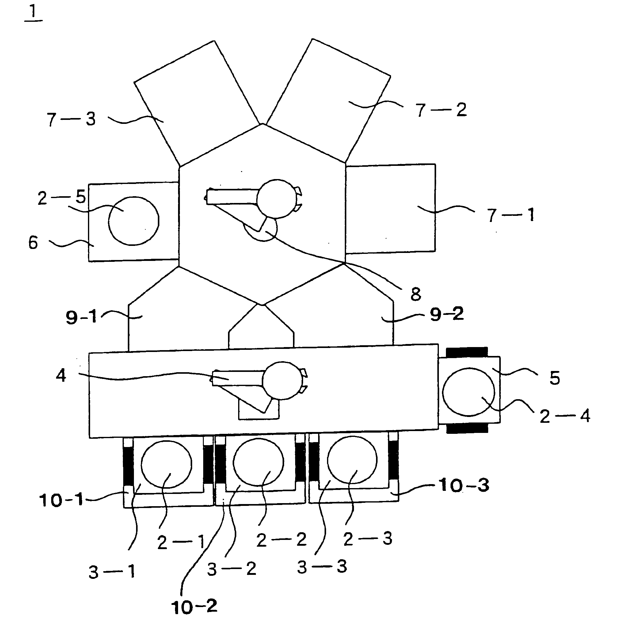
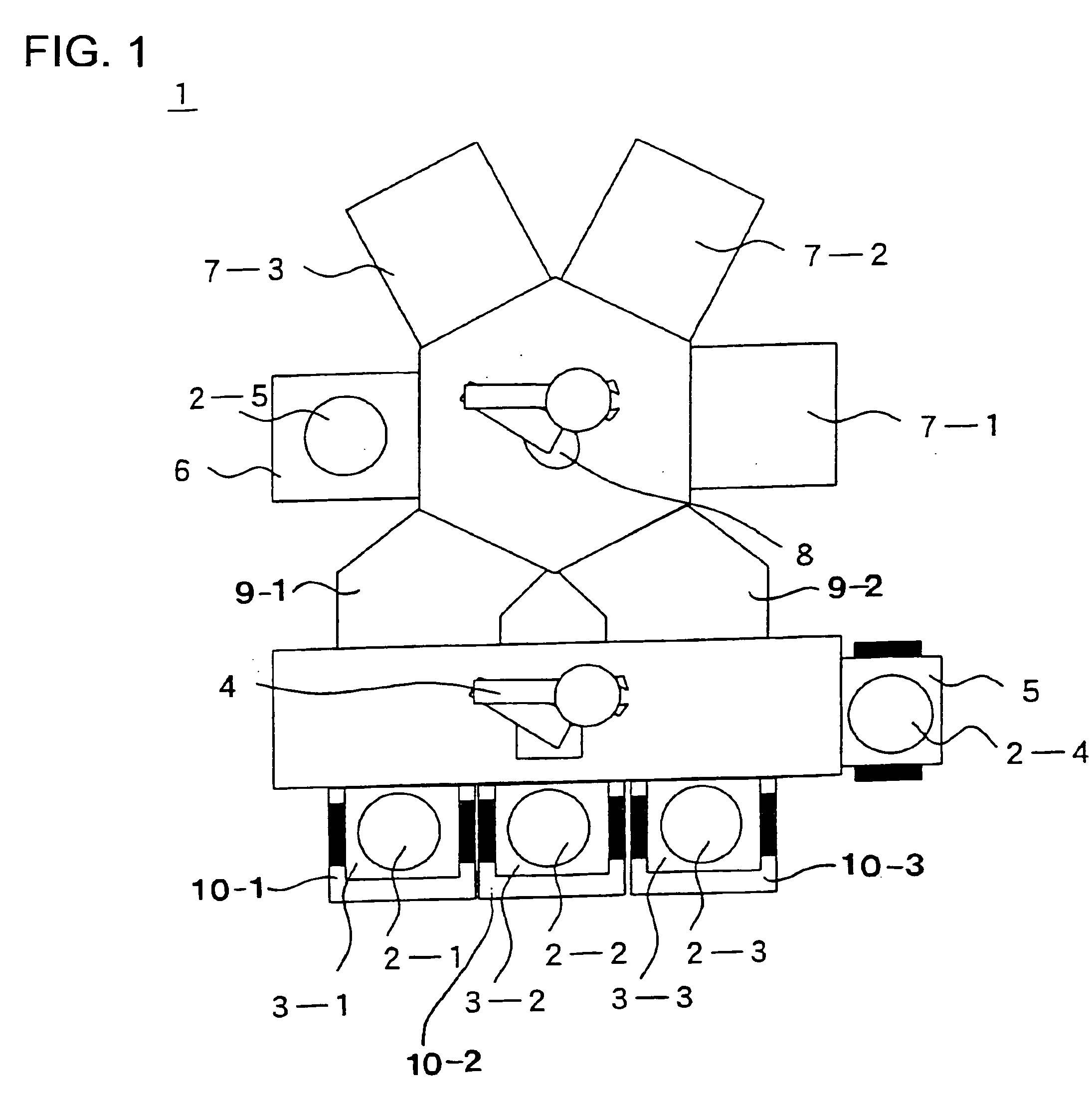
[0024] Now, the preferred embodiments of the present invention will be described. FIG. 1 shows the structure of the apparatus according to the present invention. A vacuum processing apparatus 1 comprises a plurality of vacuum processing chambers 7 (7-1, 7-2, 7-3) for subjecting samples 2 (2-1, 2-2, 2-3, 2-4, 2-5) to vacuum processing, a vacuum carriage means 8 for carrying samples 2 into and out of the vacuum processing chambers 7, switchable chambers 9 (9-1, 9-2) that can be switched between atmosphere and vacuum for carrying samples 2 into and out of the vacuum processing chamber 7, cassette supporting means 10 (10-1, 10-2, 10-3) for supporting plural cassettes 3 (3-1, 3-2, 3-3) capable of housing samples 2, a carriage means 4 capable of moving vertically and taking out a sample 2 from a given cassette on the cassette supporting means, a control unit performing carriage control for carrying the sample 2 stored in the given cassette via the carriage means 4, the switchable chamber ...


PUM


Abstract

The invention provides a vacuum processing apparatus and vacuum processing method capable of improving the yield factor of a product. A vacuum processing apparatus 1 comprises a plurality of vacuum processing chambers 7 for providing vacuum processing to a sample 2, a vacuum carriage means 8 for carrying a sample into and out of the vacuum processing chamber 7, a switchable chamber 9 capable of being switched between atmosphere and vacuum for carrying a sample into and out of the vacuum processing chamber, a cassette supporting means 10 for supporting a plurality of cassettes housing samples, a carriage means 4 capable of moving vertically for taking out a sample from a given cassette on the cassette supporting means, and a control means performing carriage control for carrying the sample in the given cassette via the carriage means, the switchable chamber and the vacuum carriage means into the vacuum processing chamber and for carrying the processed sample out of the vacuum processing chamber, wherein the apparatus is further equipped with a waiting cassette supporting means for supporting a waiting cassette 5 capable of preventing the processed samples and the unprocessed samples from being mixed in a single cassette.

Description

[0001] The present application claims priority from Japanese patent application No. 2004-097774 filed on Mar. 30, 2004, the content of which is hereby incorporated by reference into this application. FIELD OF THE INVENTION [0002] The present invention relates to a vacuum processing apparatus and vacuum processing method equipped with plural vacuum processing chambers, and more specifically, to the improvement of yield factor and operating rate of the vacuum processing apparatus and method that use corrosive gas such as halogen gas. DESCRIPTION OF THE RELATED ART [0003] Heretofore, the operating rate of a vacuum processing apparatus using at least two sets of processing devices was enhanced by utilizing the processing chambers that are operating normally as the processing path when any of the processing chambers is out of order due to malfunction etc. during operation (refer for example to patent document 1). [0004] In an apparatus having a post-processing chamber or where the etched...

Claims


Application Information

Patent Timeline
IPC IPC(8): H01L21/3065B65G1/00H01L21/00H01L21/677H01L21/68
CPCH01L21/67167H01L21/67745Y10S414/136
Inventor OONO, TAKESHINAKATA, KENJIOKIGUCHI, SHOJIUENO, TOORUOOMAE, HIDEHIROMINAMI, SHIGEHARUKAI, YOSHITAKA
Owner HITACHI HIGH-TECH CORP
Why Eureka
Try Eureka