Cryogenic temperature cool storage device and refrigerator

a technology of cryogenic temperature and cool storage device, which is applied in the direction of refrigeration machines, indirect heat exchangers, light and heating apparatus, etc., can solve the problems of high associated production cost, unsatisfactory refrigeration performance in the vicinity of 4.2 k, and low efficiency, and achieve the effect of significantly improving the refrigeration performance in the range of 3 to 10 k

Active Publication Date: 2005-10-13
SUMITOMO HEAVY IND LTD +1
View PDF5 Cites 28 Cited by
  • Summary
  • Abstract
  • Description
  • Claims
  • Application Information

AI Technical Summary

Benefits of technology

[0004] The present invention aims to resolve the conventional problems described above, with an object of providing an ultra-low temperature regenerator and a refrigerator, which utilize a novel regenerator material that enables a large improvement in refrigeration performance from 3 to 10 K when compared with conventional metal based magnetic regenerator materials, as well as providing a refrigeration system that uses such an ultra-low temperature regenerator and refrigerator.
[0012] Addition of an additive can be effective in improving the mechanical strength of a magnetic material used in the present invention. As shown in FIG. 3, addition of Al or Zr to Gd3O2S (at a weight ratio of no more than 10% relative to the Gd2O2S) causes no significant variation in the temperature dependency of the specific heat, and the material is still ideal for obtaining good refrigeration performance at 3 to 10 K. On the other hand, by adding Al or Zr, the Pickers hardness, which indicates the hardness of the Gd2O2S, improved from approximately 400 to approximately 900, meaning that even if subjected to a heavy impact during use in a refrigerator, the likelihood of separation or powdering is reduced markedly. In those cases where alumina (Al2O3) is used as an additive, the weight ratio of the alumina relative to Gd2O2S is preferably no more than 20%.
[0032] In the present invention, a ceramic magnetic material with a large specific heat in the vicinity of 4 to 10 K is used as the regenerator material for the regenerator. Accordingly, the refrigeration performance in a range from 3 to 10 K can be significantly improved in comparison with conventional metal based magnetic regenerator materials.

Problems solved by technology

However, as shown by the example of HoCu2 in FIG. 1, because these metal based magnetic regenerator materials do not have an adequately large specific heat in the vicinity from 4.2 K to 7 K, their refrigeration performance in the vicinity of 4.2 K is unsatisfactory.
Furthermore, these metal based magnetic regenerator materials also suffer other problems in that the associated production costs are high, meaning they are not cheap.

Method used


Image

  • Cryogenic temperature cool storage device and refrigerator
  • Cryogenic temperature cool storage device and refrigerator
  • Cryogenic temperature cool storage device and refrigerator

Examples


first embodiment

[0050] As shown in FIG. 4 (an overall view), FIG. 5 (a detailed view of a cooling section), and FIG. 6 (a cross-sectional view of a two-stage regenerator), the present invention involves the use of the present invention within a two-stage GM refrigerator.

[0051] In FIG. 4, high pressure gas from a compressor 11 is supplied to a two-stage GM refrigerator 1 through a high pressure gas line 12, and is recovered at a low pressure port of the compressor 11, through a low pressure gas line 13. As shown in FIG. 5, a first stage regenerator 2 and a second stage regenerator 3, housed within a first stage cylinder 25 and a second stage cylinder 35 respectively, are driven by a drive motor 14 shown in FIG. 4, and move up and down in a vertical direction.

[0052] As shown in FIG. 5, regenerator materials 24 and 34 are used to fill respective regenerator outer casings 23 and 33, and in this embodiment, the first stage regenerator material 24 is a wire mesh of a copper alloy.

[0053] As shown in FIG...

second embodiment

[0057] the present invention, applied to a two-stage pulse tube refrigerator, is shown in FIG. 8 (an overall view) and FIG. 9 (a cross-sectional view of a second stage regenerator).

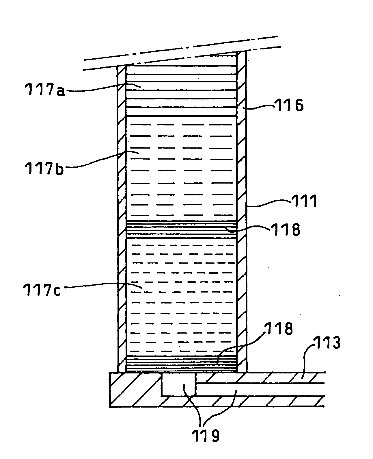
[0058] In FIG. 8, high pressure gas from a compressor 41 is supplied to a two-stage pulse tube refrigerator 4 through a high pressure gas line 42, a high-low pressure gas switching valve unit 44, and a connection line 45, and is recovered at a low pressure port of the compressor 41, through a low pressure gas line 43 and the same valve unit 44. As shown in FIG. 9, a first stage regenerator 51 and a second stage regenerator 61 comprise, respectively, regenerator outside pipes (stainless steel pipe) 56 and 66, and regenerator materials 57 and 67 filled therein.

[0059] The low temperature ends of the respective regenerators 51 and 61 are connected to respective cooling stages 52 and 62, and are connected through to respective pulse tubes 53 and 63 of the stages, via gas passages 58 and 68 respectively provid...

fourth embodiment

[0069] the present invention, applied to a 3-stage pulse tube refrigerator, is shown in FIG. 11 (a cross-sectional view of the refrigerator) and FIG. 12 (a cross-sectional view of the regenerators of each stage).

[0070] The 3-stage pulse tube refrigerator 5 of this embodiment is essentially the same as the pulse tube refrigerator4 of the second embodiment, with the points of difference being that a third stage regenerator 71 is connected directly to the end of the second stage regenerator 61, and the fact that the low temperature end of this third stage regenerator 71 is connected to the low temperature end of a third stage pulse tube 73 via a third cooling stage 72. The construction of the third stage regenerator 71, the third cooling stage 72, the third stage pulse tube 73, and a third stage phase adjustment section 74, which is connected via a connection line 75, are the same as the equivalent components in the first and second stages of the second embodiment. In FIG. 12, the refe...


PUM


Abstract

The refrigeration performance in a range from 3 to 10 K can be improved in comparison with conventional metal based magnetic regenerator materials. The refrigerator is provided with a regenerator utilizing at least one magnetic material including a rare earth element and sulfur as the regenerator material.

Description

TECHNICAL FIELD [0001] The present invention relates to an ultra-low temperature regenerator and a refrigerator, and more particularly to an ultra-low temperature regenerator and a refrigerator that use a novel regenerator material to improve the refrigeration capabilities, and are ideally suited to use in GM (Gifford-McMahon) cycle refrigerators, Stirling cycle refrigerators, pulse tube refrigerators, Vuilleumier cycle refrigerators, Solvay cycle refrigerators, Ericsson cycle refrigerators, and refrigeration systems that use these refrigerators in a precooling stage, as well as a refrigeration system, a cryogen liquefaction apparatus, a cryogen recondensation apparatus, a superconducting magnet equipment, a superconducting device cooling equipment, a cryogenic panel, a cryogenic heat shield, and a cooling apparatus for use in the field of space technology that utilize this ultra-low temperature regenerator and refrigerator. BACKGROUND ART [0002] In conventional regenerator type ult...

Claims


Application Information

Patent Timeline
Patent Type & Authority Applications(United States)
IPC IPC(8): F25B9/00F25B9/14
CPCF25B9/00F25B9/02F25B9/145F25B2309/003F25B2309/1415
Inventor LI, RUINUMASAWA, TAKENORI
Owner SUMITOMO HEAVY IND LTD
Why Eureka
Try Eureka