Enhanced photovoltaic module

a photovoltaic module and photovoltaic technology, applied in the direction of photovoltaics, electrical devices, semiconductor devices, etc., can solve the problems of high cost, heavy tempered glass, and many inherent problems in the use of glass plates, and achieve economics in manufacture and installation.

Inactive Publication Date: 2005-10-13
CHEUNG OSBERT H
View PDF1 Cites 62 Cited by
  • Summary
  • Abstract
  • Description
  • Claims
  • Application Information

AI Technical Summary

Benefits of technology

[0012] The configuration of the present invention comprises a new combination of layers of protective and adhesive materials which, will 1) insure the efficient transmission of sunlight upon one or more solar cells encapsulated in the module, 2) will possess the ability to remain in their originally processed positions throughout the life of the module, and 3) be economical in manufacture and installation. The configuration also includes a truly self-adhesive material of the peel and seal type which, will permit a module to be applied to a reinforced back sheet or panel mounted on a building or vehicle supporting structure at ambient temperature and slight hand pressure. The invention is also directed a new method for fabrication and installing a photovoltaic module which will insure that the same will not shift or slide relative to its supporting structure upon which the module is installed, and that the layers comprising the module will not separate during handling, bending or rolling or during heating after installation due to high ambient temperatures.

Problems solved by technology

However, while glass is impermeable to moisture and therefore is ideal as a weathering covering and as a rigid structural support for the solar cell, the use of glass plates present many inherent problems, most notably, that the glass plate cannot be bent.
In addition, specifically tempered glass is heavy and expensive.
These arrangements not only increase the cost, but also add more weight on the building structure which must be reinforced to accommodate accordingly.
In addition to being heavier, the applications of glass type photovoltaic elements tend to be limited by how these elements are manufactured through the production line.
Therefore, once the glass is tempered, the size for the photovoltaic module can not be changed.
To make variable sizes of tempered glass for elements becomes very costly and time consuming.
The high cost of making varieties of elements sizes is one of the main challenges of the photovoltaic industry.
Another limitation is that glass type photovoltaic elements allow very few applications which can be used in the installation associated with motion or as part of a moving body, such as vehicles, marine vessels, and portable electrical equipment.
As will be apparent, the fragile nature of the glass plates increases the possibility of break down.
Photovoltaic modules without a glass cover, could cause potential damage on polycrystalline cells unless the solar cells are of the flexible type.
This patent discloses rubberized asphalt type adhesive for the application and is labeled as “Self-Adhesive Photovoltaic module.” The inherent potential problem with the use of asphalt and tar substrate materials in supporting modules on roof tops, etc., is that during hot sun exposure, the substrate will soften thereby may cause shifting, and in extreme cases, severe sliding movement, or even detachment of the module relative to their original, intended operative position.
These prospects have restricted the installation of such module panels in the vertical, near vertical, or even to lesser degree orientations.
To overcome these prospects, some installations have necessitated the use of superstructures designed and configured to support photovoltaic panels on roof structure utilizing hardware, metallic channels, fasteners, and the like, thus adding labor costs for mounting the panel and for the mounting hardware.
The problem for the high temperature method is that the reinforced material must also be tolerated at such high temperature during the adhering process.
Because of this heating unfortunately, many rigid, lightweight, low cost reinforcing materials can not be used in this method.
As previously mentioned, the problem with this application is that asphalt can become soft at high temperature and brittle at cold temperature.
This material is only suitable on flat roofs, or on roofs with certain degree slope relative to the horizontal plane.
Otherwise, when mounted in vertical or near vertical orientation, it may present potential problems for the possibility of sliding or even dislodgement of the module.

Method used


Image

  • Enhanced photovoltaic module
  • Enhanced photovoltaic module
  • Enhanced photovoltaic module

Examples


Embodiment Construction

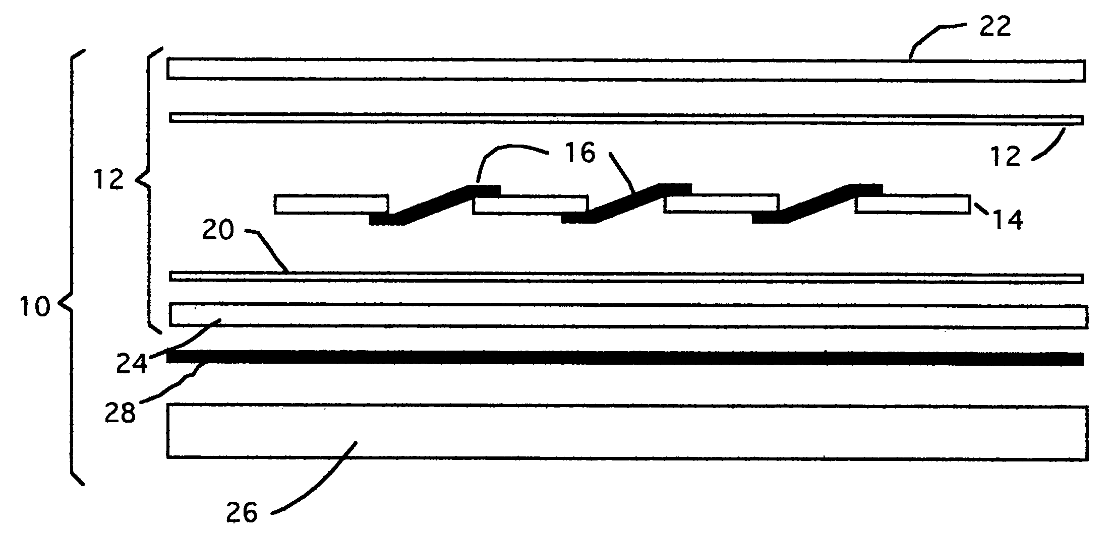
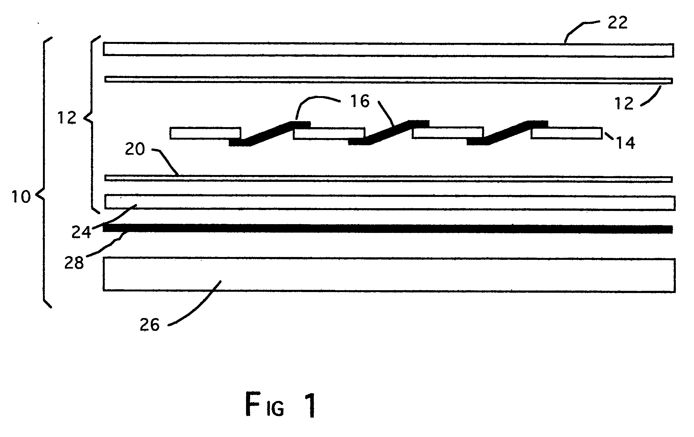
[0015] As shown in FIG. 1, a photovoltaic module, generally indicated by the reference numeral 10 and devised in accordance with the present invention, includes a photovoltaic element 12 having a photovoltaic device comprising a plurality of solar cells 12, each of which may be a monocrystalline cell, multicrystalline cell, amorphorus silicone photovoltaic cell, or a compound semiconductor photovoltaic cell. The preferred solar cells in the present invention are of the multicrystalline type since it is of the least cost, and is able to sustain a longer period in which to generate electricity. The solar cells 14 are connected by suitable electrical conductors 16 which, are connected to a central electrical network, not forming a part of the invention. The cells are encapsulated within the element by a set of layers 18, 20, to be described herewith. The first or upper layer 18 is adhesively arranged on the surfaces of the solar cells which directly receive sunlight for producing elect...


PUM


Abstract

A photovoltaic module and a method for its fabrication and installation on a support structure for the production of electrical current thereon is disclosed utilizing layers of materials which encapsulate one or more solar cells, and secure the same to a reinforcing sheet. Materials are utilized and manufacturing steps are practiced which maintain a long useful life of the module, will insure the stability for the layers to maintain their fixed positions during handling and installing of the module. Such materials are of less cost than those used in conventional modules, and the process steps are simple and easy to perform. The method permits the easy installation of the module on a supporting structure at room temperature prior to mounting the same at installation sites

Description

FIELD OF THE INVENTION [0001] The present invention relates to the field of photovoltaic electrical generating modules of the type having a photovoltaic element encapsulating one or more solar cells adapted to generate electrical current in response to the impingement of sunlight thereon, and more particularly to modules, which include photovoltaic elements, arranged as panels for mounting. The modules are flexible, of low cost material, lightweight and may be easily customized and fabricated to size for most applications. BACKGROUND OF THE INVENTION [0002] Photovoltaic technology is considered a promising, clean energy source due to the fact that it does not use such environmental unfriendly sources of combustion such as fossil fuels and nuclear energy, and to the fact its sole energizing medium is sunlight which Is unlimited in both availability and quantity. In recent years, photovoltaic devices in the form of solar cells have become increasingly popular for supplying limited ele...

Claims


Application Information

Patent Timeline
Patent Type & Authority Applications(United States)
IPC IPC(8): H01L31/00
CPCH01L31/048Y02E10/50
Inventor CHEUNG, OSBERT H.
Owner CHEUNG OSBERT H
Why Eureka
Try Eureka