Method and apparatus for removing a thermal barrier coating from a power generation component

a technology of thermal barrier coating and power generation components, which is applied in the field of cleaning systems, can solve the problems of large-scale turbine, generator, boiler components, being taken off, and affecting the operation of large-scale power generation plants and jet engines, and achieve the effect of reducing the radioactivity of the surfa

Inactive Publication Date: 2005-10-13
KILBURN CHRIS A
View PDF0 Cites 49 Cited by
  • Summary
  • Abstract
  • Description
  • Claims
  • Application Information

AI Technical Summary

Benefits of technology

[0014] In a fourth aspect, the invention provides a method of reducing the radioactivity of a surface comprising positioning a laser remotely from the surface, providing a laser workhead that receives a laser signal from the laser via a light guide, positioning the workhead proximate the surface such that the workhead can deliver a laser beam onto the surface, and moving the workhead along the surface while the laser beam ablates the surface to effectuate a reduction in the radioactivity of the surface.

Problems solved by technology

Maintaining and cleaning large-scale turbine, generator, and boiler components (referred to collectively as “power generation components”) such as those found in power generation plants and jet engines, represent a significant operational cost.
Unfortunately, this results in these machines being taken “off-line” for a period of time for servicing.
Every hour of downtime results in significant lost revenue, particularly in power generation plants and the like.
Accordingly, the need for quick and efficient, waste-reducing cleaning and analysis techniques for turbine and generator components remains an ongoing challenge.
The process of completely disassembling such a machine is a complex and expensive process.
In the past, effectively cleaning certain components without a complete disassembly was almost impossible given that a foreign material (e.g., blast media) would need to be introduced, therefore potentially contaminating other parts of the machine.
For example, turbine parts, such as turbine blades, may require the removal of built up debris that is reducing the overall efficiency of the machine, or impeding inspection.
The above-described methods are not only labor intensive, but also pose an environmental hazard.
Workmen are exposed to hazardous chemical cleaners and are subjected to potential exposure to airborne contamination of the media used for blast cleaning.
The blast cleaning media can escape from the enclosure and contaminate the surrounding area.
In addition, such blast cleaning may release asbestos particles, a common component of insulation in turbine windings and stator bars.

Method used


Image

  • Method and apparatus for removing a thermal barrier coating from a power generation component
  • Method and apparatus for removing a thermal barrier coating from a power generation component
  • Method and apparatus for removing a thermal barrier coating from a power generation component

Examples


Embodiment Construction

Overview

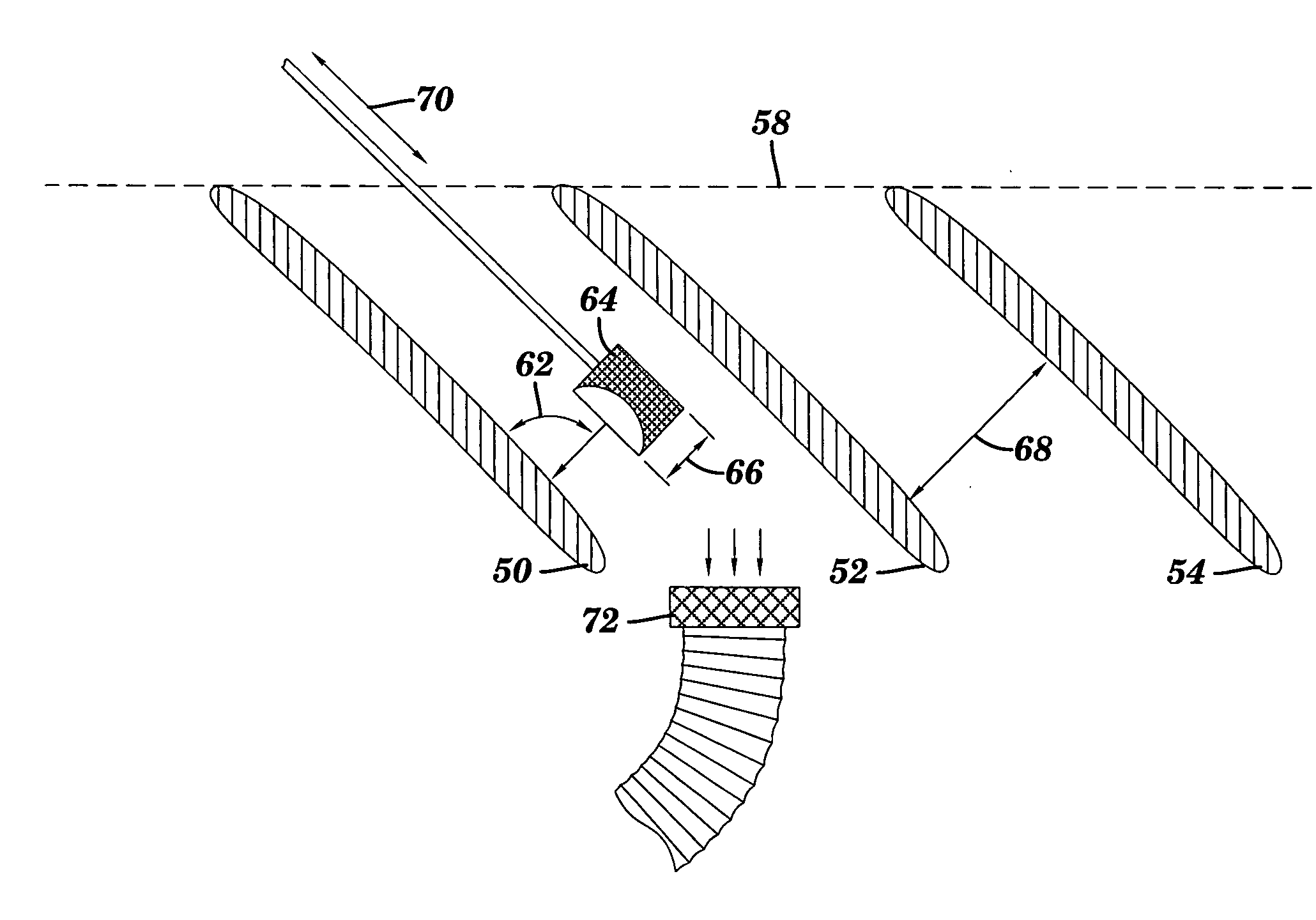
[0026] The present invention provides various laser-based systems and methods for cleaning boiler, generator, and turbine parts (collectively “power generation components”) or other surfaces requiring cleaning and / or removal of a thermal barrier coating (TBC). As noted above, cleaning such components is critical for maintaining performance, and is also a prerequisite for performing non-destructive evaluations (NDEs). It should be understood that the invention could be applied to any type of mechanical power system, e.g., boilers, gas turbines, steam turbines, jet engines, compressors, etc., that utilizes parts which require cleaning.

Turbine Blades

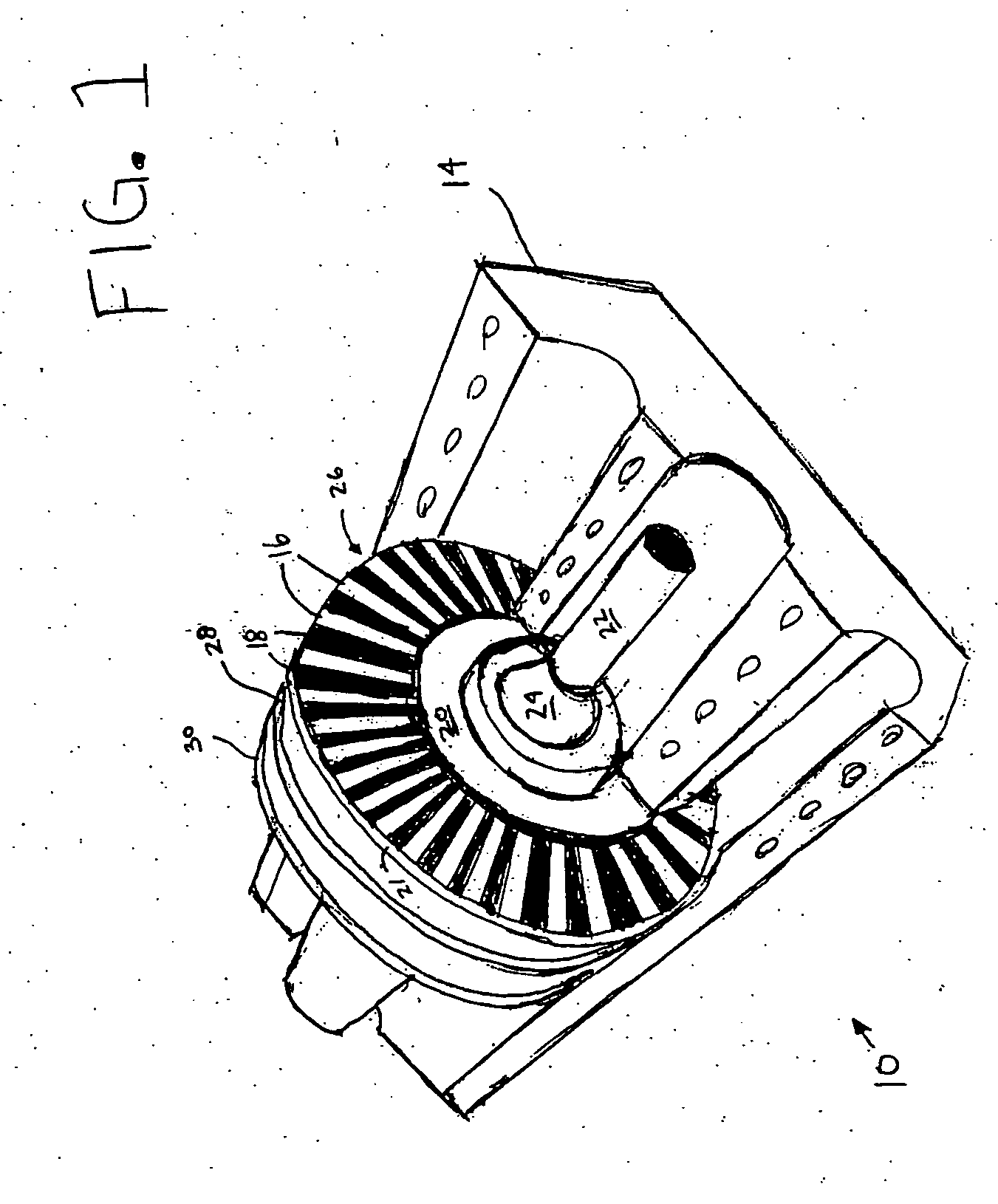
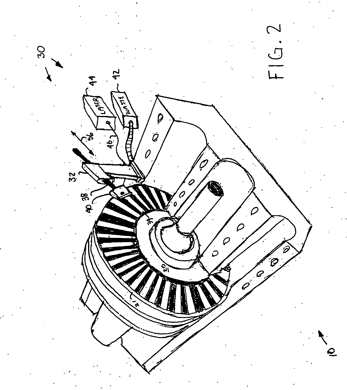
[0027] Referring now the drawings, FIG. 1 depicts an exemplary turbine system 10 seated in the bottom portion of a turbine housing 14. The turbine system 10 would typically sit on a turbine deck (not shown). The top portion of the housing (not shown) has been removed to expose the inner workings of the turbine system 10. The de...


PUM

PropertyMeasurementUnit
poweraaaaaaaaaa
diameteraaaaaaaaaa
diameteraaaaaaaaaa

Abstract

The present invention provides a cleaning system and method that utilizes a portable workhead to direct a pulsed laser beam to a surface of a generator, turbine or boiler component or similar surface requiring cleaning and/or removal of a thermal barrier coating (TBC). In a first aspect, the invention provides a laser-based cleaning system for removing a thermal barrier coating from a power generation component, comprising a laser positioned remotely from the power generation component for generating a laser signal, a laser workhead capable of being positioned proximate the power generation component, wherein the laser workhead can deliver a laser beam onto the power generation component surface to cause the thermal barrier coating to be removed, and a light guide that delivers the laser signal from the laser to the laser workhead.

Description

CROSS REFERENCE TO RELATED APPLICATIONS [0001] This is a continuation-in-part application of prior co-pending U.S. patent application Ser. No. 10 / 883,198, filed Jul. 1, 2004, which is a continuation-in-part application of U.S. patent application Ser. No. 10 / 273,043, filed Oct. 17, 2002, now U.S. Pat. No. 6,759,627.BACKGROUND OF THE INVENTION [0002] 1. Technical Field [0003] The present invention relates to cleaning systems, and more particularly relates to a laser-based ablation system and method for use thereof. [0004] 2. Related Art [0005] Maintaining and cleaning large-scale turbine, generator, and boiler components (referred to collectively as “power generation components”) such as those found in power generation plants and jet engines, represent a significant operational cost. The combination of intense stresses placed on the components and contaminants introduced into the components requires that such large-scale systems follow a strict maintenance and inspection schedule. Unf...

Claims


Application Information

Patent Timeline
Patent Type & Authority Applications(United States)
IPC IPC(8): F01D25/00B08B7/00B23K26/14B23K26/36B23K26/12
CPCB08B7/0042B23K2101/001B23K26/0643B23K26/0648B23K26/0665B23K26/12F01D25/002Y02T50/67F05D2230/13B23K26/128B23K26/064B23K26/1462B23K26/142Y02T50/6765B23K26/032Y02T50/60
Inventor KILBURN, CHRIS A.
Owner KILBURN CHRIS A
Why Eureka
Try Eureka