Power factor impoving circuit

a technology of power factor and impoving circuit, which is applied in the direction of electric variable regulation, process and machine control, instruments, etc., can solve the problems of increasing the loss of the switch q, increasing the loss of the cr absorber, and increasing the loss of the switch, so as to achieve low noise and high efficiency

Inactive Publication Date: 2005-10-13
SANKEN ELECTRIC CO LTD
View PDF3 Cites 23 Cited by
  • Summary
  • Abstract
  • Description
  • Claims
  • Application Information

AI Technical Summary

Benefits of technology

[0016] The present invention has an object to provide a power factor correction circuit that enables a switch to execute zero-current switching and zero-voltage switching for thereby making it possible to achieve miniaturization, high efficiency and low noises.

Problems solved by technology

However, with the power factor correction circuit shown in FIG. 1, during the turned-on or turned-off states of the switch Q1, overlapped portions occur between the voltage Q1v and the current Q1i of the switch Q1, resulting in an issue with the occurrence of increased switching losses.
During recovery time, the diode D1 remains in a short-circuited state, increasing losses of the switch Q1.
Moreover, due to the additional provision of a CR absorber comprised of a resistor and a capacitor for the purpose of suppressing the spike voltage resulting when the switch Q1 is turned off, also causing the CR absorber to have increased losses.
Further, the spike voltage and the spike current cause noises to occur.
A noise filter for reducing such noises is largely sized in structure, causing hindrance to the achievement of miniaturization and high efficiency of the switching power-supply.

Method used


Image

  • Power factor impoving circuit
  • Power factor impoving circuit
  • Power factor impoving circuit

Examples


first embodiment

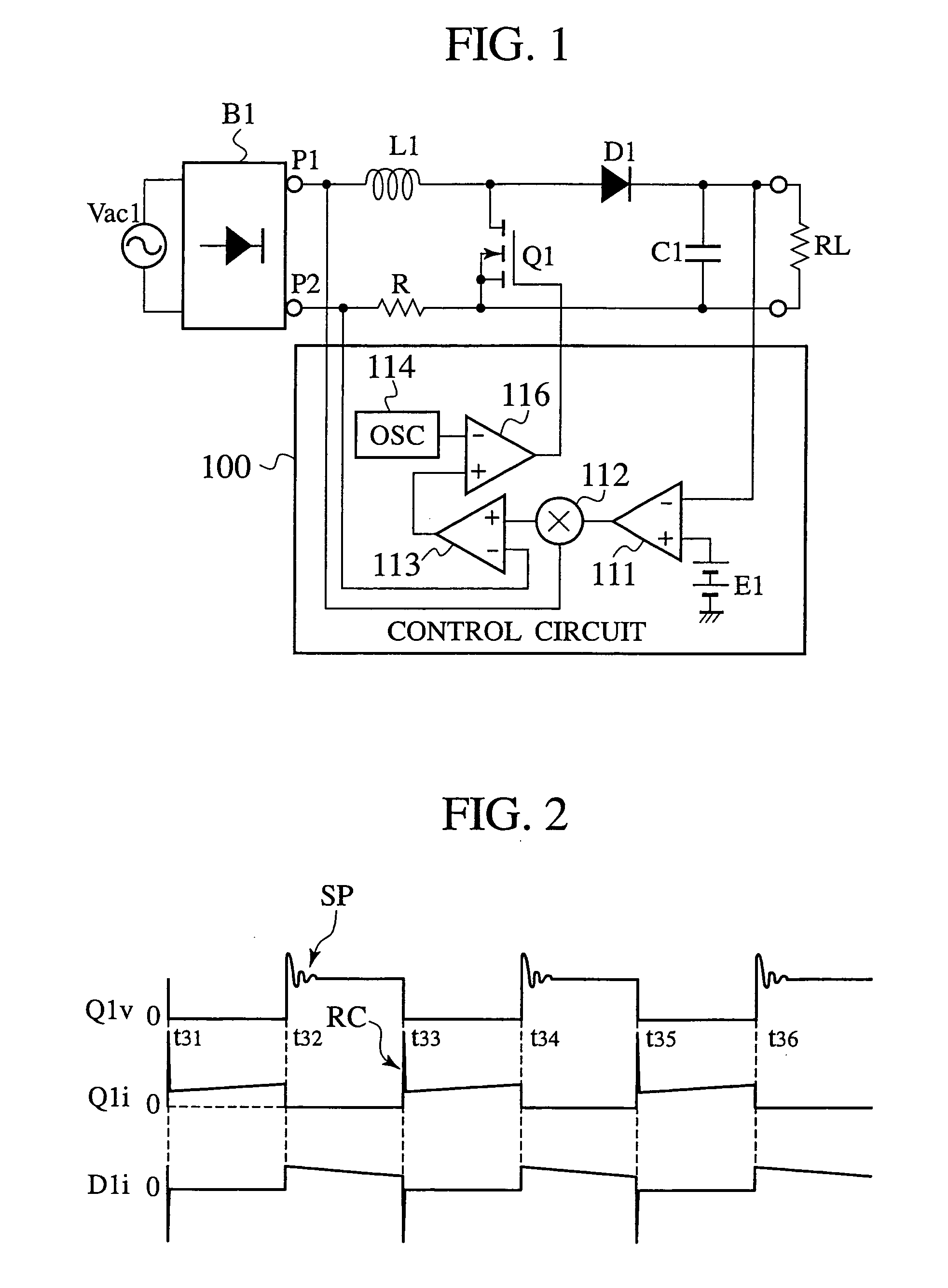
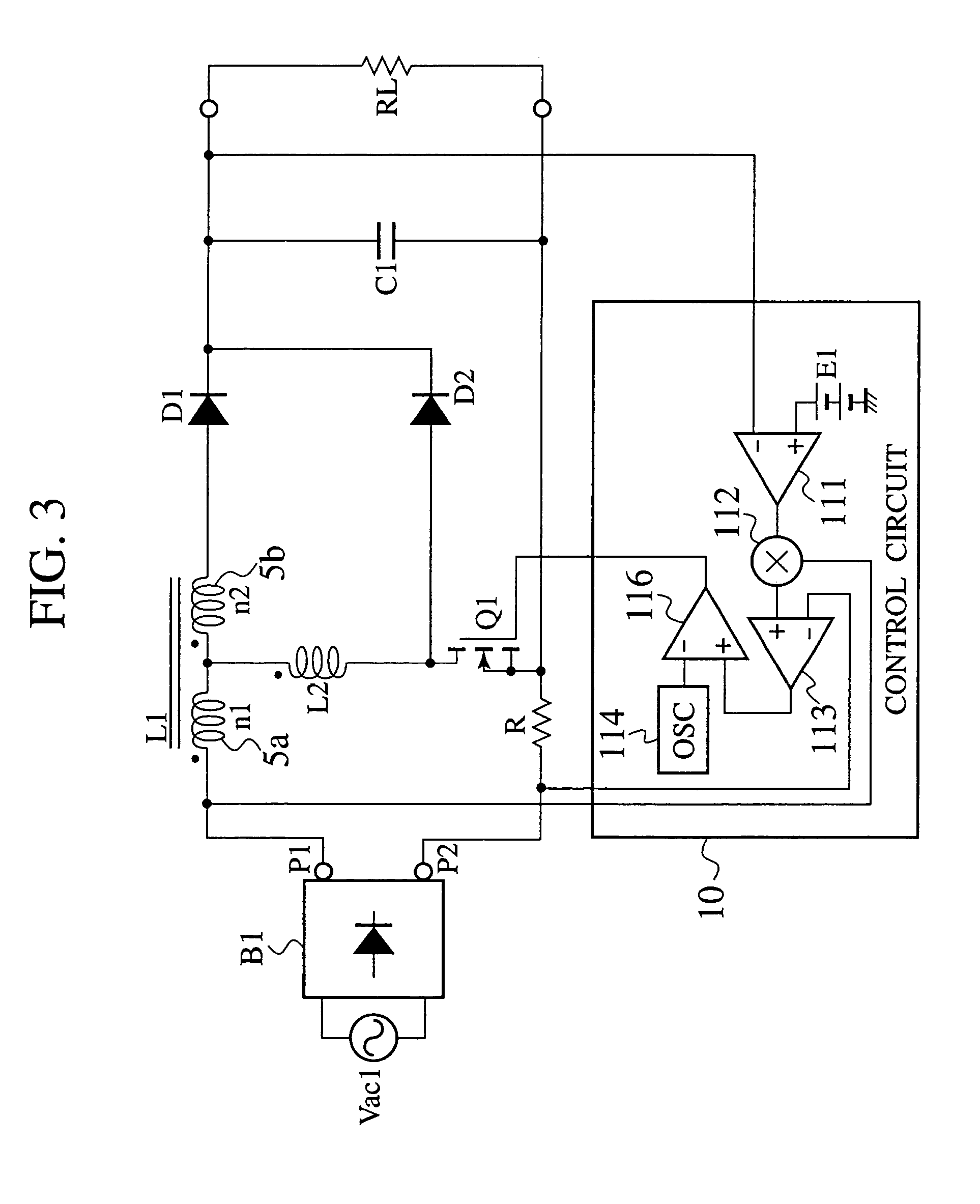
[0056] A power factor correction circuit of a first embodiment includes a zero-current switching reactor connected to a main switch in series to allow the main switch to achieve ZCS (zero-current switching) during a turned-on state for thereby reducing losses resulting from a recovery cycle of a rectifying diode such that current gradually changes for thereby performing switching operations at high efficiency and low noises.

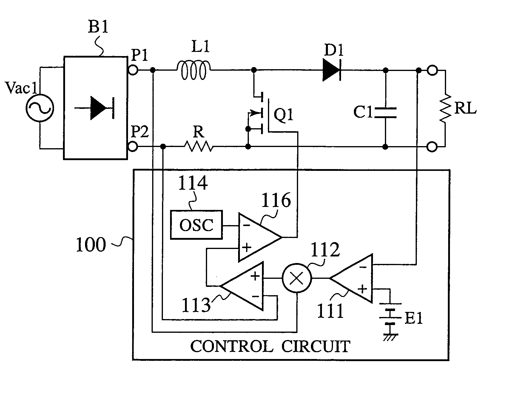
[0057]FIG. 3 is a circuit structural view of the power factor correction circuit of the first embodiment. In FIG. 3, a full wave rectifier circuit B1 is connected to an Alternating current power-supply Vac1 to rectify an Alternating current power-supply voltage, received from the Alternating current power-supply Vac1, into a DC voltage that is applied to a positive electrode output terminal P1 and a negative electrode output terminal P2.

[0058] Connected between the positive electrode output terminal P1 and the negative electrode output terminal P2 of the full w...

second embodiment

[0088]FIG. 10 is a circuit structural view of a power factor correction circuit of a second embodiment. The power factor correction circuit of the second embodiment, shown in FIG. 10, differs from the power factor correction circuit of the first embodiment, shown in FIG. 3, in that the ZCS reactor L2 is connected between the booster reactor L1 and the diode D1. The ZCS reactor L2 may be structured with a leakage inductor between the booster winding 5a and the wind-up winding 5b of the booster reactor L1.

[0089]FIG. 11 is a structural view showing a structure of the booster reactor L1 provided in the power factor correction circuit of the second embodiment. The booster reactor L1, shown in FIG. 11, which has a central leg 30c and side legs 30a, 30b, includes a core (iron core) 30 composed of E-shaped core elements, each made of magnetic material, in which a magnetic circuit is formed. The core 30 is made of a magnetic body such as ferrite having high permeability with less iron losse...

third embodiment

[0105]FIG. 13 is a circuit structural view of a power factor correction circuit of a third embodiment. The power factor correction circuit of the third embodiment contemplates to render the power factor correction circuit of the second embodiment, shown in FIG. 10, operative such that the switch Q1 executes the ZCS operation during a turned-on period while, at the same time, collecting electrical charge of a snubber capacitor C2 and permitting the switch Q1 to execute ZVS (zero-voltage switching) operation during turned-off of the switch Q1. This enables reduction in losses resulting from the recovery of the rectifying diode and permits the electric current to slowly change, enabling switching operation at high efficiency with low noises. That is, by charging the snubber capacitor C2 via a diode D5 when the switch Q1 is turned off, the rising of the voltage of the switch Q1 is alleviated to decrease losses during the turned-off state of the switch Q1 while minimizing the occurrence ...


PUM


Abstract

A power factor correction circuit includes; a series circuit connected to a positive-electrode output terminal P1 and negative-electrode output terminal P2 of a full-wave rectifying circuit B1, which rectifies an having current power-supply voltage of an alternating current power-supply Vac1, and including a booster winding 5a and a wind-up winding 5b wound on a booster reactor L1, a diode D1 and a smoothing capacitor C1; a series circuit, connected between the positive-electrode output terminal P1 and the negative-electrode output terminal P2 and having the booster winding 5a, a ZCS reactor L2 and a switch Q1; a diode D2 connected between a junction, between the switch Q1 and the ZCS reactor L2, and the smoothing capacitor C1; and a control circuit 10 that controllably turns the switch Q1 on and off for controlling an output voltage of the smoothing capacitor C1 to a given voltage.

Description

TECHNICAL FIELD [0001] The present invention relates to a power factor correction circuit for use in a switching power-supply with high efficiency, low noises and high power factor. BACKGROUND ART [0002]FIG. 1 is a circuit structural view of a power factor correction circuit disclosed in Japanese Patent Application No. 2000-37072. In the power factor correction circuit shown in FIG. 1, connected to both output terminals of a full-wave rectifying circuit B1, which rectifies an alternating current power-supply voltage of an alternating current power-supply Vac1, is a series circuit that is comprised of a booster reactor L1, a switch Q1 composed of a MOSFET, and a current detection resistor R. Connected across both terminals of the switch Q1 is a series circuit that is comprised of a diode D1 and a smoothing capacitor C1, and connected across the smoothing capacitor C1 is a load RL. The switch Q1 is PWM controlled by a control circuit 100 to be turned on and off. [0003] The current det...

Claims


Application Information

Patent Timeline
Patent Type & Authority Applications(United States)
IPC IPC(8): H02M1/00H02M1/42
CPCH02M1/4208Y02B70/126H02M1/4225Y02B70/10Y02P80/10H02M1/0064H02M3/155
Inventor TSURUYA, MAMORU
Owner SANKEN ELECTRIC CO LTD
Why Eureka
Try Eureka