Optical disc drive apparatus, information reproducing or recording method
- Summary
- Abstract
- Description
- Claims
- Application Information
AI Technical Summary
Benefits of technology
Problems solved by technology
Method used
Image

Examples
first embodiment
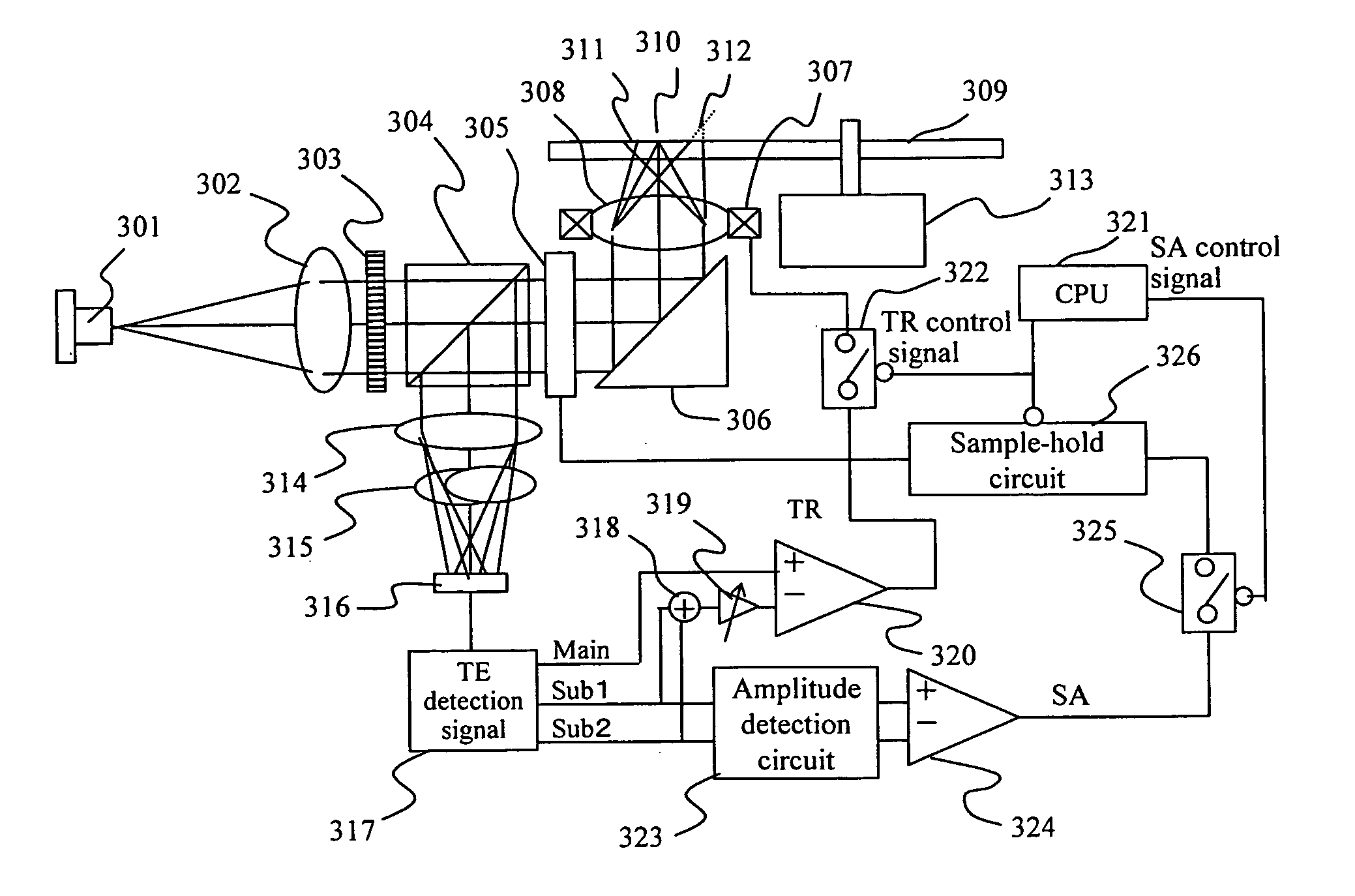
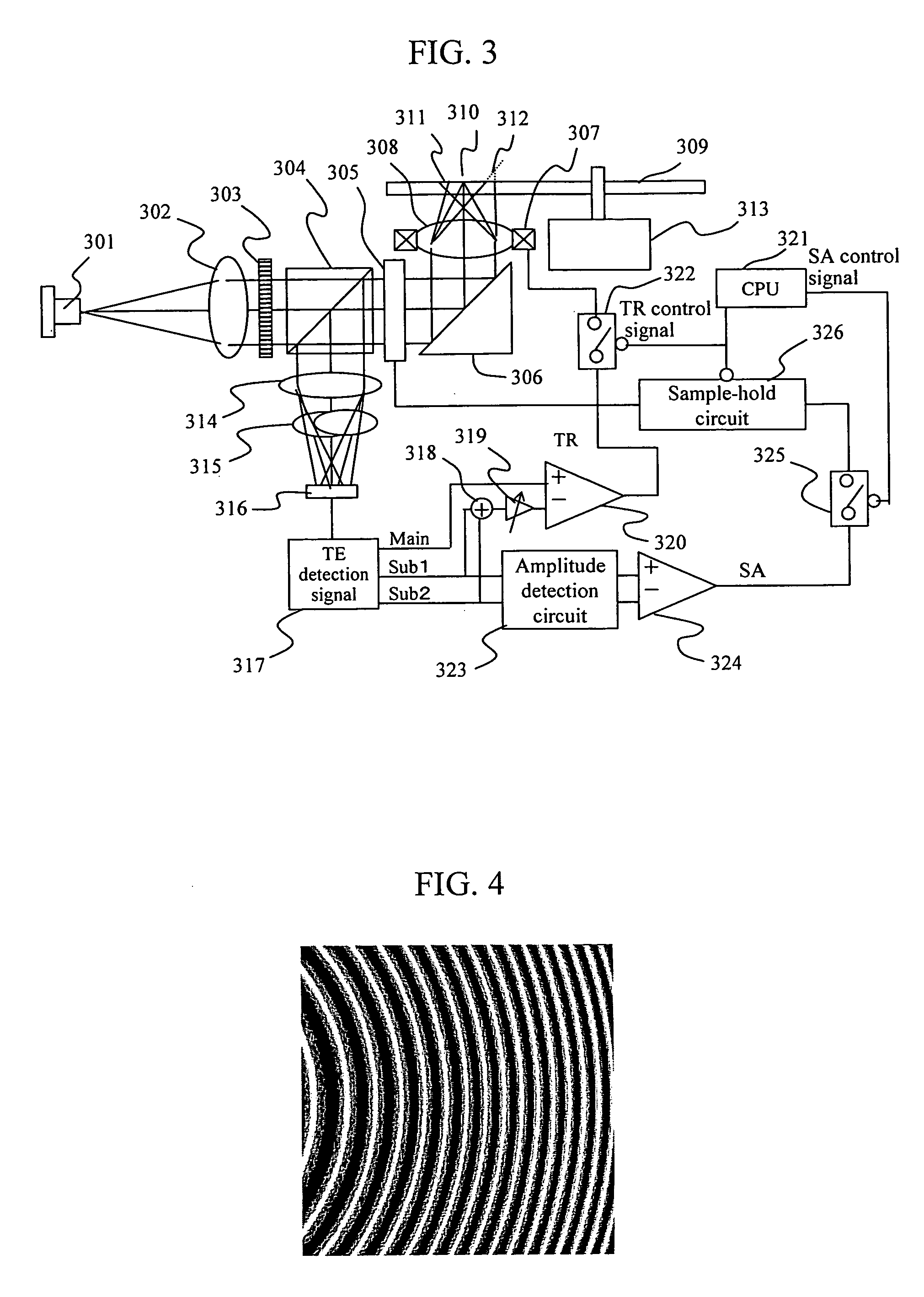
[0059] Hereunder, the first embodiment of the present invention will be described with reference to FIG. 3. A beam emitted from a semiconductor laser 301 is transformed into parallel beams by a collimator lens 302, then separated by a curvilinear diffracted grating 303 into a 0th order beam that goes linearly, a +1st order diffracted beam converged slightly by the action of the curvilinear grating lens with respect to the 0th order beam, and a −1st order diffracted beam that diverges slightly with respect to the 0th order beam. In order to simplify the description here, however, those diffracted beams just output from the curvilinear diffracted grating 303 are not illustrated. After that, those beams are passed through a beam splitter 304 and a spherical aberration compensator 305, then reflected by a rising mirror 306, and finally condensed on an optical disk 309 through an objective lens 308 provided in a tracking actuator 307 as a main beam 310 and sub-beams 311 and 312. The two ...
second embodiment
[0073]FIG. 16 illustrates beam spot patterns detected by the photodetector shown in FIG. 3 in the second embodiment of the present invention. In this embodiment, the two sub-beam receiving regions are provided as four-divided beam receiving regions 1601 and 1602. As a result, the focus error signals of the two sub-beams are added to the focus error signal of the main beam to calculate a focus error signal, thereby canceling the disturbance to be exerted on the focus error signal when the main spot crosses the disk guiding groove. At that time, because each of the sub-beams are defocused from the main beam, the calculation gain G1 / G2 comes to differ between the focus error calculation and the differential push-pull signal calculation. The differential push-pull gain G2 may be determined so that the sum of the intensities of the two sub-beams is almost balanced with the intensity of the main beam. A gain that is about double the G2 is found to be the best to cancel the disturbance to ...
PUM
 Abstract
Description
Claims
Application Information
 - Generate Ideas
- Intellectual Property
- Life Sciences
- Materials
- Tech Scout
- Unparalleled Data Quality
- Higher Quality Content
- 60% Fewer Hallucinations
Browse by: Latest US Patents, China's latest patents, Technical Efficacy Thesaurus, Application Domain, Technology Topic, Popular Technical Reports.
© 2025 PatSnap. All rights reserved.Legal|Privacy policy|Modern Slavery Act Transparency Statement|Sitemap|About US| Contact US: help@patsnap.com