
Method and apparatus for continuously manufacturing calibrated round or profiled glass tubes

Active Publication Date: 2005-10-13
SCHOTT AG
View PDF16 Cites 19 Cited by
  • Summary
  • Abstract
  • Description
  • Claims
  • Application Information

AI Technical Summary

Benefits of technology

[0011] It is an object of the present invention to provide a method and a apparatus for continuously manufacturing calibrated glass tubes whereby glass tubes having a predetermined inner profile can be manufactured precisely, inexpensively and flexibly.
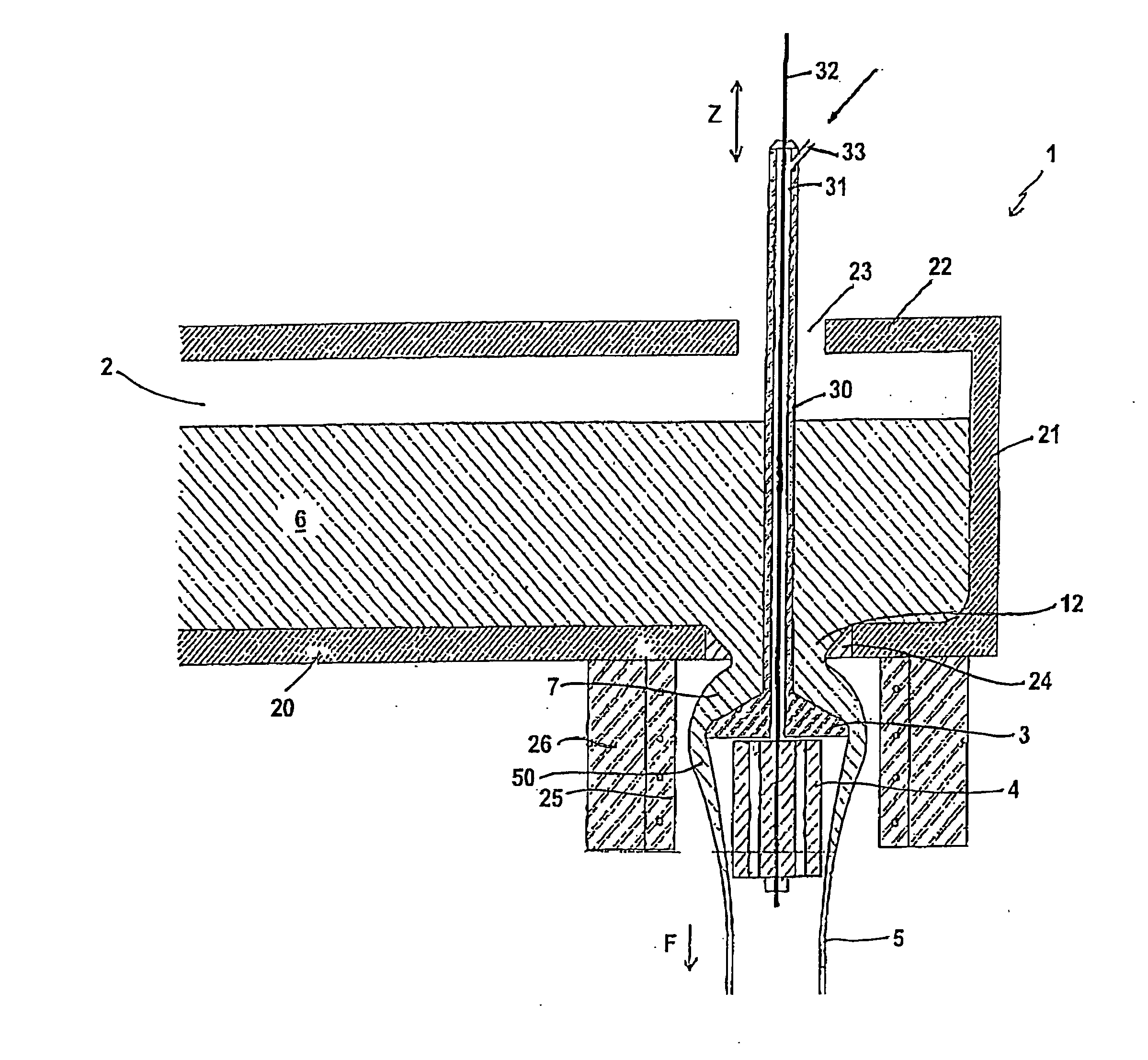
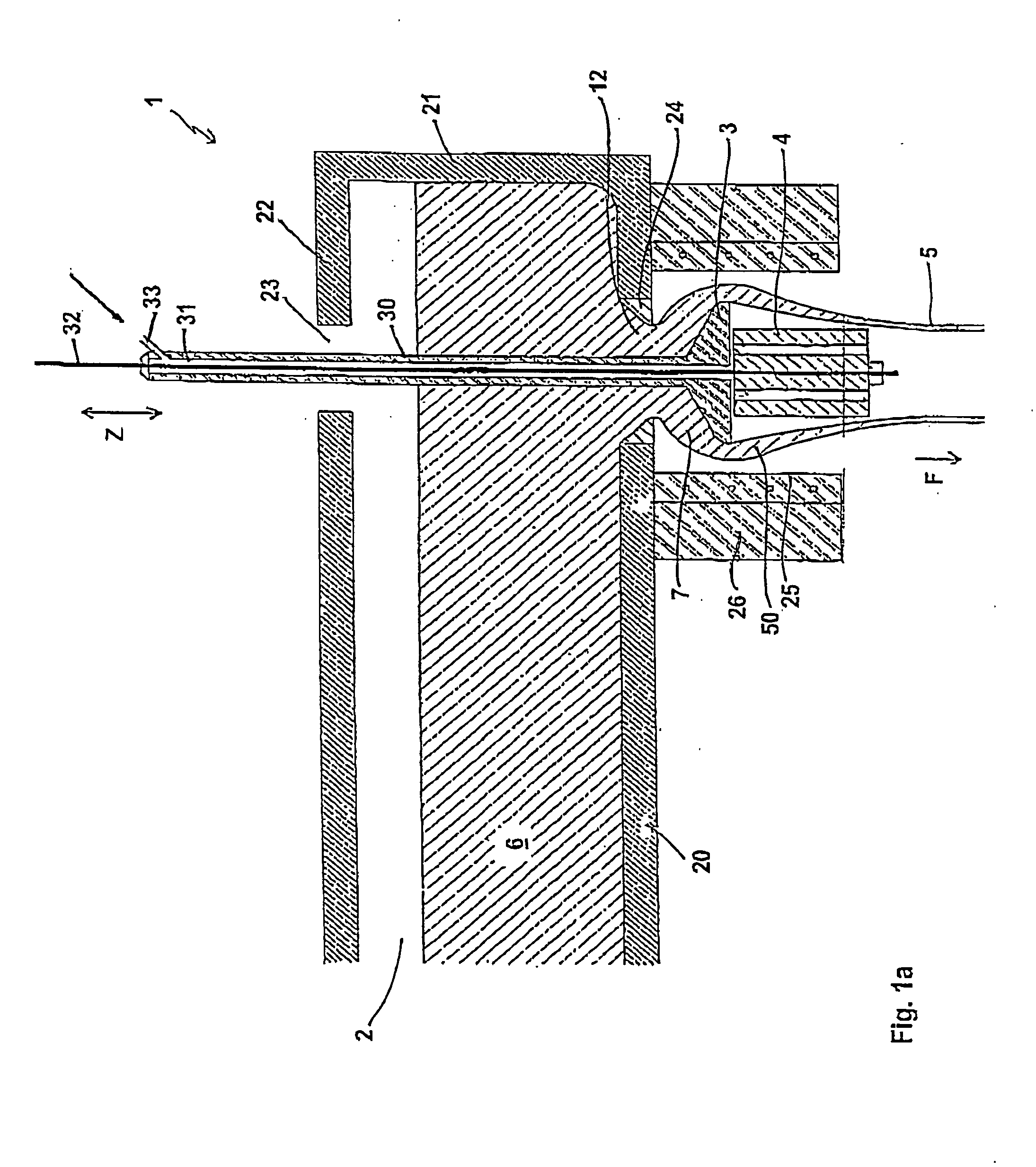
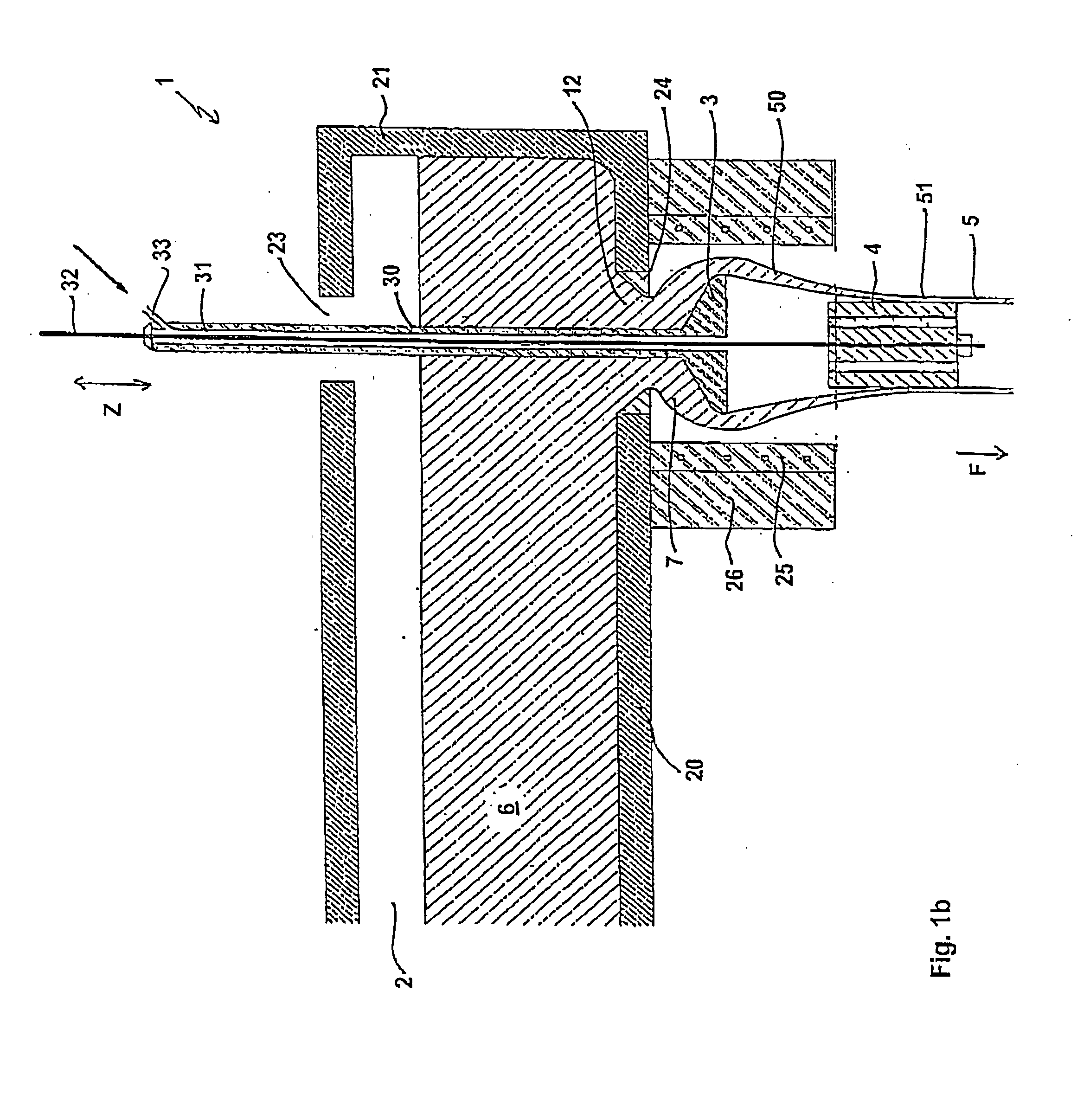
[0013] According to the invention, a separate profile forming body (i.e. a body defined by closed surfaces in three dimensional space for forming the profile of the glass tube) having a centre substantially in alignment with the centre of the shaping body is thus provided so that the shaping of the hollow, still-deformable drawing bulb and the further profiling of the same to form a calibrated round or profiled glass tube can take place in different zones. Thus, the parameters of the drawing method can be predetermined in a more variable and controlled fashion. At the same time, however, the profile forming body according to the invention can be simply replaced by another suitable profile forming body so that the inner profile of the glass tube to be manufactured can easily be changed. A drawing device according to the invention is thus suitable for manufacturing a plurality of different calibrated round or profiled glass tubes which makes the drawing method or drawing apparatus less expensive and more flexible.
[0017] The further shaping of the inner profile of the drawing bulb preferably only takes place at the lower partial section of the profile forming body positioned thereafter, but not over its entire length. The length of the lower partial section is chosen such that the predetermined inner profile of the glass tube is formed sufficiently stably and the walls of the glass tube after leaving the profile forming body are already sufficiently solid or stable so that no subsequent deformation of the glass tube occurs downstream of the profile forming body. In this case, the profile forming body contributes to a further preferably rapid cooling of the glass tube which according to the invention represents an additional degree of freedom during the manufacture of glass tubes. In particular, expensive cooling measures for cooling a profile forming body can be superfluous according to the invention.
[0019] The distance between the shaping body and the profile forming body can be varied. Thus, the drawing bulb can be stretched or upset in a suitable manner, which according to the present invention has a direct influence on the wall thickness of the glass tube. E.g. the wall thickness of the glass tube can be made smaller by stretching the drawing bulb whereas the wall thickness of the glass tube can be made larger by upsetting the drawing bulb. In particular, the distance between the shaping body and the profile forming body can be varied according to the invention, such that, to match the respective process parameters, the profile forming body can always be moved into a region where the constriction of the drawing bulb is still sufficiently deformable but the calibrated round or profiled glass tube thus formed no longer undergoes any deformation or is not very strongly deformed, for example, stretched, downstream of the profile forming body. Since the profile forming body according to the invention can be axially adjusted, the drawing method according to the invention can very rapidly be converted to glass tubes having a different wall thickness as well as to a different drawing velocity of the glass tube.
[0020] A profile forming body shaft is preferably held displaceably in a longitudinal bore of a shaping body shaft for displacing the profile forming body relative to the shaping body. The longitudinal bore is matched to the shaft of the profile forming body so that said body is guided straight in the longitudinal bore, i.e. during a displacement only its axial position but not its radial position is changed. This ensures that in all positions of the profile forming body, shaping body and profile forming body are arranged in alignment so that the drawing bulb can abut very uniformly against the profile forming body and uniform wall thicknesses can be formed. Special mounting or retaining means are provided to guide the shaft of the profile forming body straight in the longitudinal bore.
[0022] The longitudinal bore or a longitudinal bore provided within the holding device of the profile forming body is preferably designed so that process air and / or inert protective gas, for example, nitrogen or argon can be passed to the profile forming body. The inert gas prevents oxidation and / or corrosion on the underside of the profile forming body which could otherwise result in uncontrolled rounding at the edge of the profile forming body and thus rough or streaked glass surfaces.

Problems solved by technology

Because of the fundamentally different process parameters in most cases, the principles applied in discontinuous manufacturing methods cannot or at least cannot easily be transferred to continuous manufacturing methods so that they cannot serve as a stimulus for the person skilled in the art to improve continuous manufacturing methods.
Thus, this method frequently no longer meets the present requirements for the precision and tolerances of calibrated round or profiled glass tubes.
It is comparatively difficult to find suitable ranges of parameters for manufacturing glass tubes having different profiles and requires a great deal of experience which at least makes it expensive to completely automate the method.
Re-equipping the melting furnace to manufacture glass tubes having different profiles is comparatively expensive.
Nevertheless, glass tubes manufactured by the Vello method have tolerances which increasingly are no longer suitable for the present applications.
This is comparatively expensive.
The tolerances which can be achieved using this method frequently no longer meet the present requirements.
In order that a glass tube having a constant wall thickness can be produced, the drawing bulb and the drawing mandrel must be rotated synchronously, which is expensive.
Furthermore, it is comparatively expensive to control the parameters of the device so that the still-deformable glass tube can be suitably deformed by the nozzle system.
This apparatus is only suitable for manufacturing calibrated round glass tubes and conversion to other inside or outside diameters is comparatively expensive.
In particular, the distance to the shaping body can not be varied.
Thus, the method is only suited for a relatively narrow range of working temperatures and drawing velocities.
However, the position of the profile shaping body relative to the shaping body cannot be varied.
The parameters of the drawing method therefore can not be varied sufficiently.

Method used


Image

  • Method and apparatus for continuously manufacturing calibrated round or profiled glass tubes
  • Method and apparatus for continuously manufacturing calibrated round or profiled glass tubes
  • Method and apparatus for continuously manufacturing calibrated round or profiled glass tubes

Examples


exemplary embodiment 1

[0066] It can be seen from the following exemplary embodiment that glass tubes having more precise profiles and smaller tolerances can be manufactured using the drawing method according to the invention.

[0067] For this purpose, a glass tube having otherwise the same parameters was drawn using the conventional down-draw method without using the profile forming body according to the invention positioned downstream of a drawing needle (free forming). The conditions were selected so that a glass tube having an inside diameter of 59.25 mm should be freely formed. Measurements of the inside diameter showed that this fluctuated along the length of the glass tube between a minimum value of about 58.70 mm up to a maximum value of about 59.85 mm, corresponding to an average fluctuation of 1.15 mm in total.

[0068] For comparison, under otherwise the same conditions a calibrated glass tube was manufactured using the drawing method according to the invention i.e., with a profile forming body po...

exemplary embodiment 2

[0071] Using a method according to the present invention, calibrated glass tubes with a total length of 54 m having an outer diameter of 80 mm, a wall thickness of 2.5 mm and an inner diameter of 75 mm were drawn. More specifically, a plurality of single glass tubes with a respective length of 1.5 m was drawn. The outer diameter was measured continuously over the total tube length. In order to avoid slicing of the glass tubes, the inner diameter was measured only at the respective tube ends, as a fluctuation of the inner diameter directly results in a corresponding fluctuation of the outer diameter of the glass tube under the assumption of a constant wall thickness. The results of the measurement of the maximum and minimum outer diameter of the glass tube are summarized in FIG. 6, wherein the single glass tubes are numerated.

[0072] Referring to FIG. 6, the maximum outer diameter varied between 80.6 mm and about 80.48 mm. Furthermore, the minimum outer diameter varied between 80.55 ...


PUM

PropertyMeasurementUnit
Fractionaaaaaaaaaa
Fractionaaaaaaaaaa
Fractionaaaaaaaaaa

Abstract

The present invention relates to a method and apparatus for continuously manufacturing calibrated round or profiled glass tubes having a predetermined inner profile. In the method molten glass emerges from an outlet opening of a melt feed. The molten glass is drawn over a shaping body so as to form a hollow drawing bulb. According to the invention, the drawing bulb is drawn over a profile forming body positioned downstream of the shaping body so that inner circumferential surfaces of the drawing bulb are deformed whilst abutting against outer surfaces of the profile forming body to form the predetermined inner profile. According to the invention the distance between the shaping body and the profile forming body can be changed for varying the wall thickness of the glass tube.

Description

FIELD OF INVENTION [0001] The present invention relates to a method and apparatus for continuously manufacturing calibrated round or profiled glass tubes, especially calibrated round or profiled glass tubes having a pre-determined inner profile and / or a pre-determined outer profile. BACKGROUND OF INVENTION [0002] Glass tubes of the aforesaid type, having lengths of up to several metres are required as starting material for manufacturing a wide range of glass elements, for example, for manufacturing bottles and containers, tubular covers for illuminants and for manufacturing illuminant tubes in lighting engineering. On the one hand, it is required that these glass tubes should be produced as cheaply as possible. On the other hand, in many applications, for example in lighting engineering, there is a demand for glass tubes having precisely finished inner profiles, for example, predetermined by the technical specifications in the respective application. [0003] In the manufacture of gla...

Claims


Application Information

Patent Timeline
IPC IPC(8): C03B15/14C03B7/08C03B17/04C03B23/08
CPCY10T428/131C03B17/04
Inventor MAENNER, THOMASZIEGLER, MICHAELOTT, FRANZROSNER, GERD
Owner SCHOTT AG
Learn More