

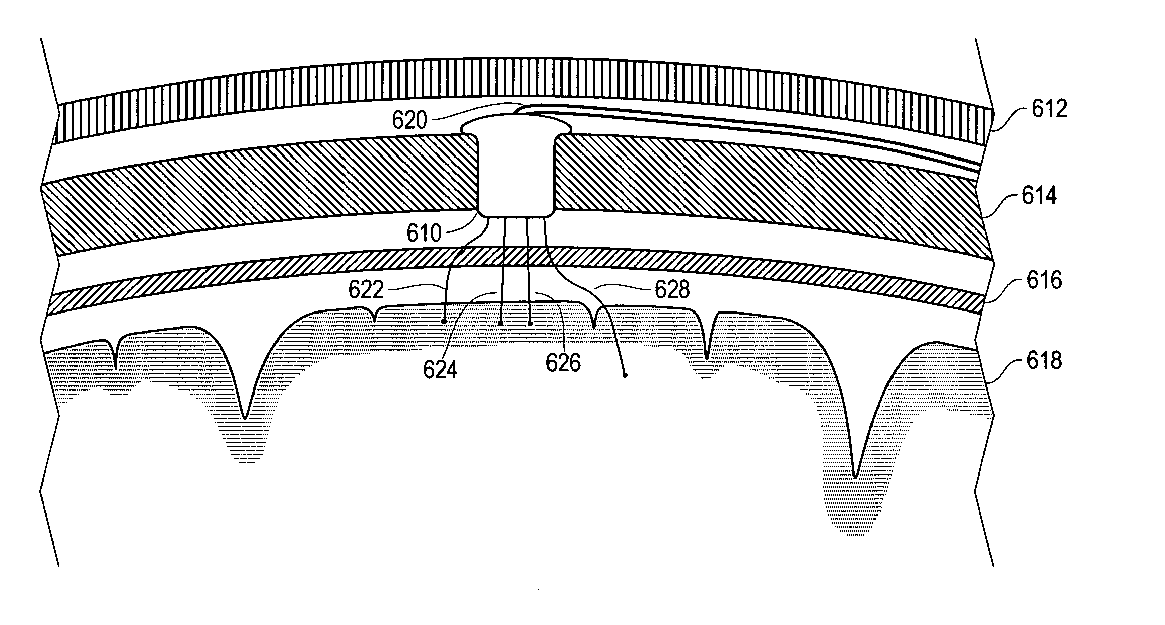
Implantable lead system with seed electrodes
a seed electrode and implantable technology, applied in the field of implantable medical leads, can solve the problems of inability to precisely localize with scalp electrodes, affecting the signal-to-noise ratio, and occupying a small space, so as to reduce the excess of slack, reduce the risk of fracture and erosion, and reduce the effect of excess slack
- Summary
- Abstract
- Description
- Claims
- Application Information
AI Technical Summary
Benefits of technology
Problems solved by technology
Method used
Image

Examples
Embodiment Construction
[0025] The invention is described below, with reference to detailed illustrative embodiments. It will be apparent that a system according to the invention may be embodied in a wide variety of forms. Consequently, the specific structural and functional details disclosed herein are representative and do not limit the scope of the invention.
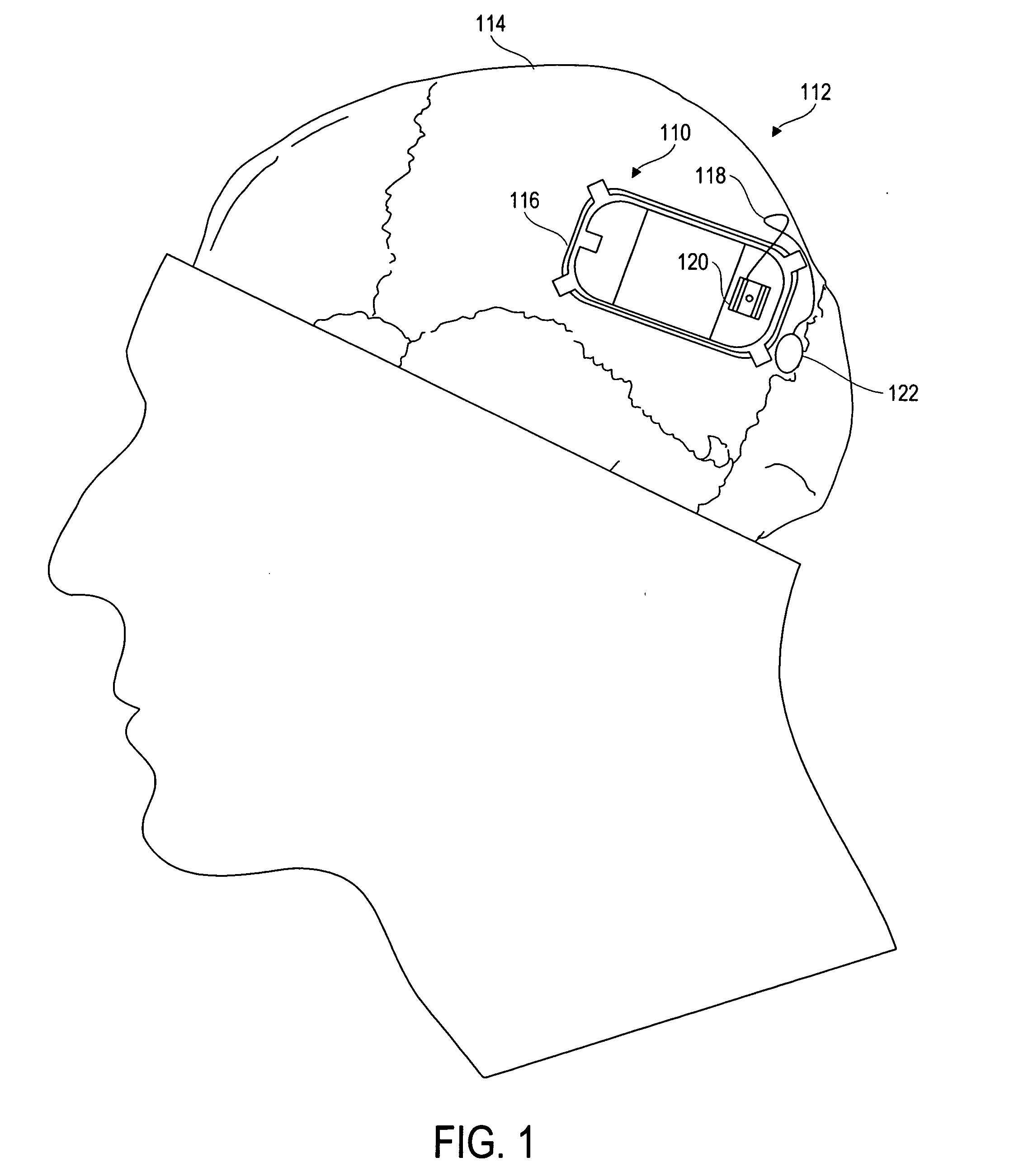
[0026] An implantable neurostimulator device 110 according to the invention, as implanted intracranially in a patient 112, is illustrated in FIG. 1. The device 110 is affixed in the patient's cranium 114 by way of a ferrule 116. The ferrule 116 is a structural member adapted to fit into a cranial opening, attach to the cranium 114, and retain the device 110.
[0027] To implant the device 110, a craniotomy is performed in the parietal bone anterior to the lambdoidal suture to define an opening slightly larger than the device 110. The ferrule 116 is inserted into the opening and affixed to the cranium 114, ensuring a tight and secure fit. The device 1...
PUM
 Abstract
Description
Claims
Application Information