Handheld diagnostic ultrasound system with head mounted display

a diagnostic ultrasound and display technology, applied in diagnostics, medical science, applications, etc., can solve the problems of inadequacies of mechanical probes and doppler modes, and achieve the effect of high integration and slender shap

Inactive Publication Date: 2005-10-13
SONOPAD
View PDF21 Cites 236 Cited by
  • Summary
  • Abstract
  • Description
  • Claims
  • Application Information

AI Technical Summary

Benefits of technology

[0048] All device operating information is confirmed displayed and fed back to the operator through the HMD such that the operator does not have to look at the control unit for visual feedback. The probe contains a freeze button so that any active image can be held on the display for closer inspection or measurement. The dual-core processor controls all diagnostic ultrasound device functions and is a highly integrated, low power “system-on-a-chip” (SOC). The dual-core processor allows functional upgrades and new features for the diagnostic ultrasound device in the field.
[0049] The diagnostic ultrasound device supports removable probes for various diagnostic requirements including, but not limited to: phased array, linear, curve linear and mecha

Problems solved by technology

Mechanical probes, however, are not appropriate for Doppl

Method used


Image

  • Handheld diagnostic ultrasound system with head mounted display
  • Handheld diagnostic ultrasound system with head mounted display
  • Handheld diagnostic ultrasound system with head mounted display

Examples


Embodiment Construction

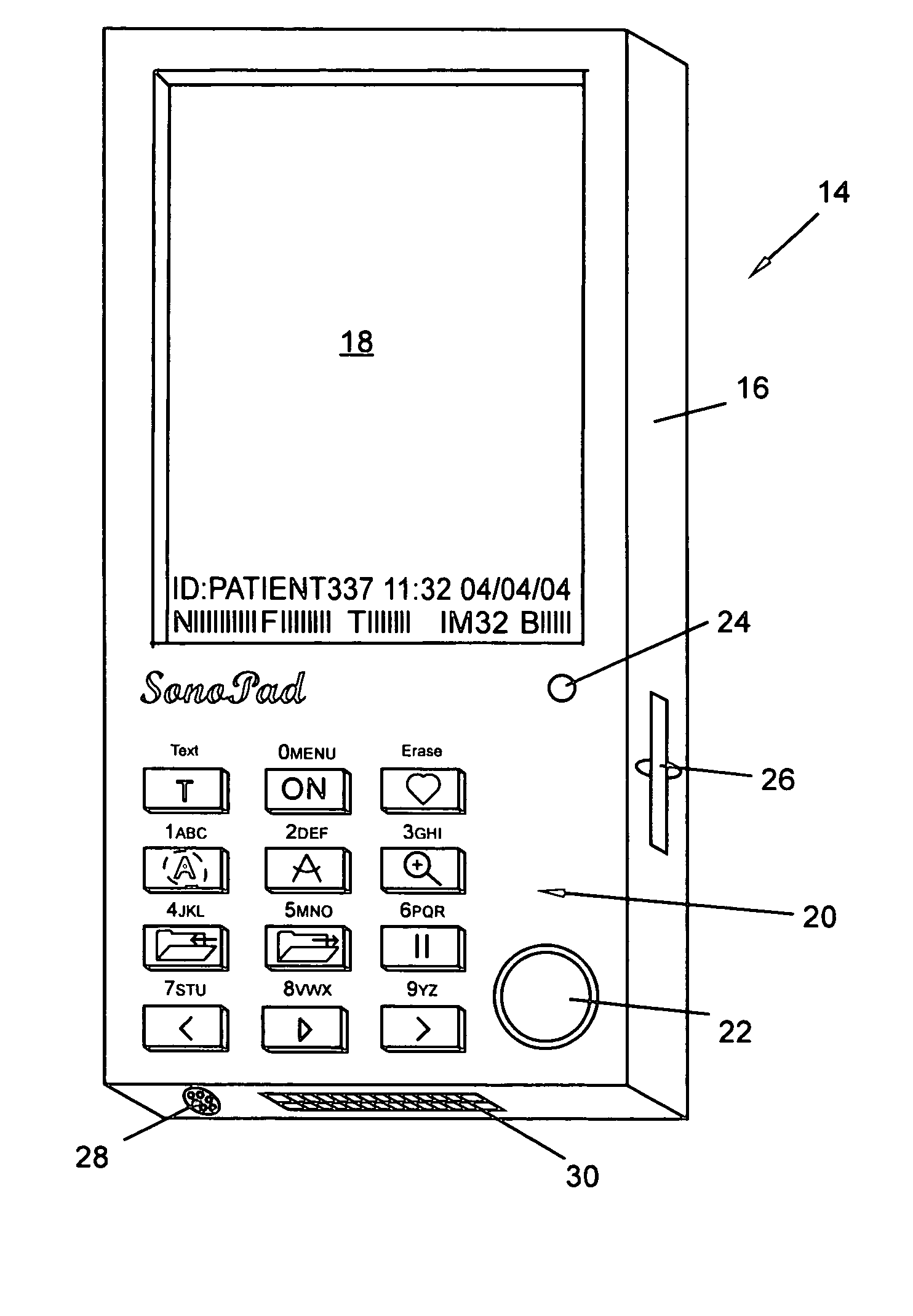
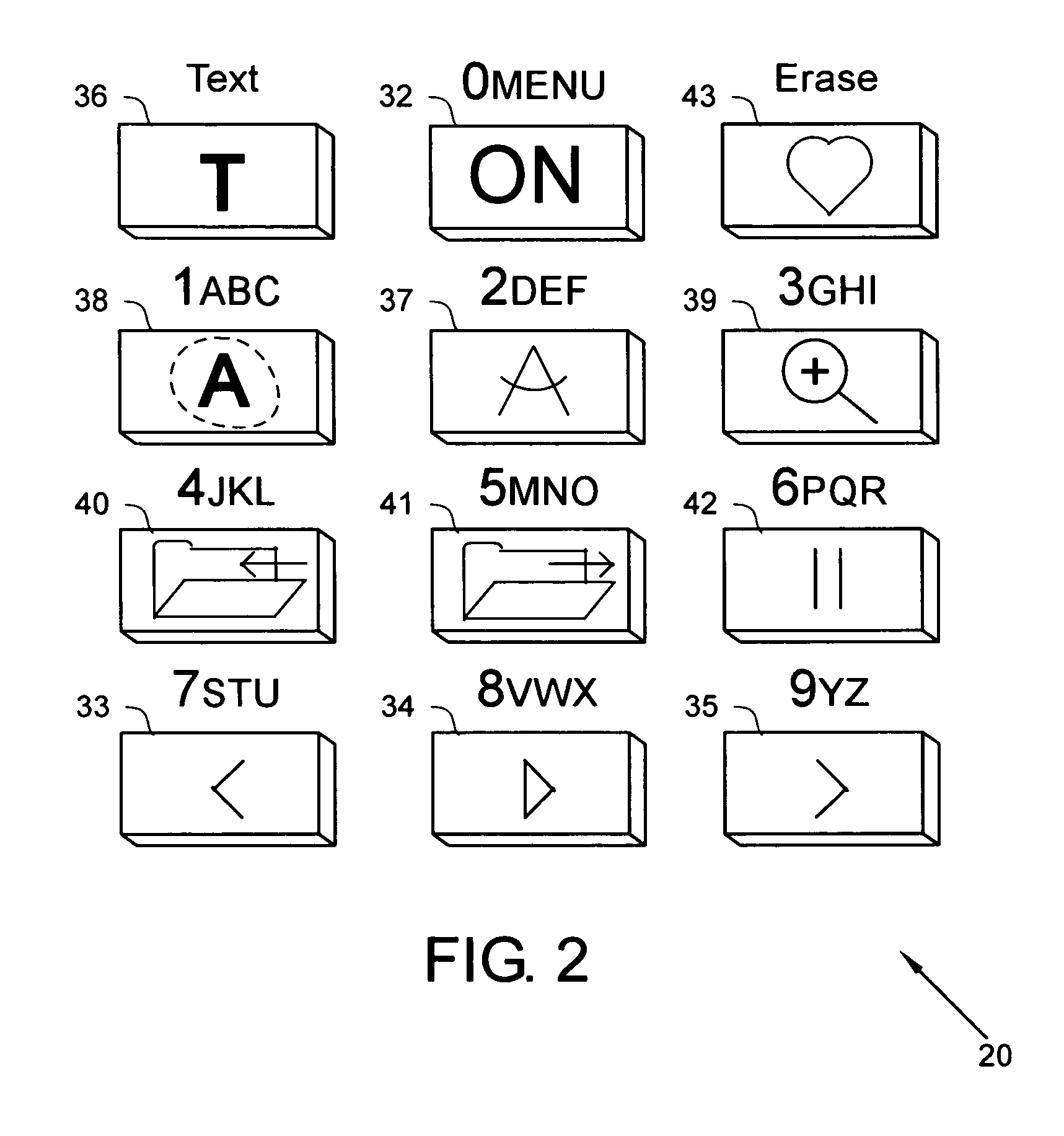
[0064]FIG. 1 is a perspective top view of a diagnostic_ultrasound_device in accordance with the present invention.

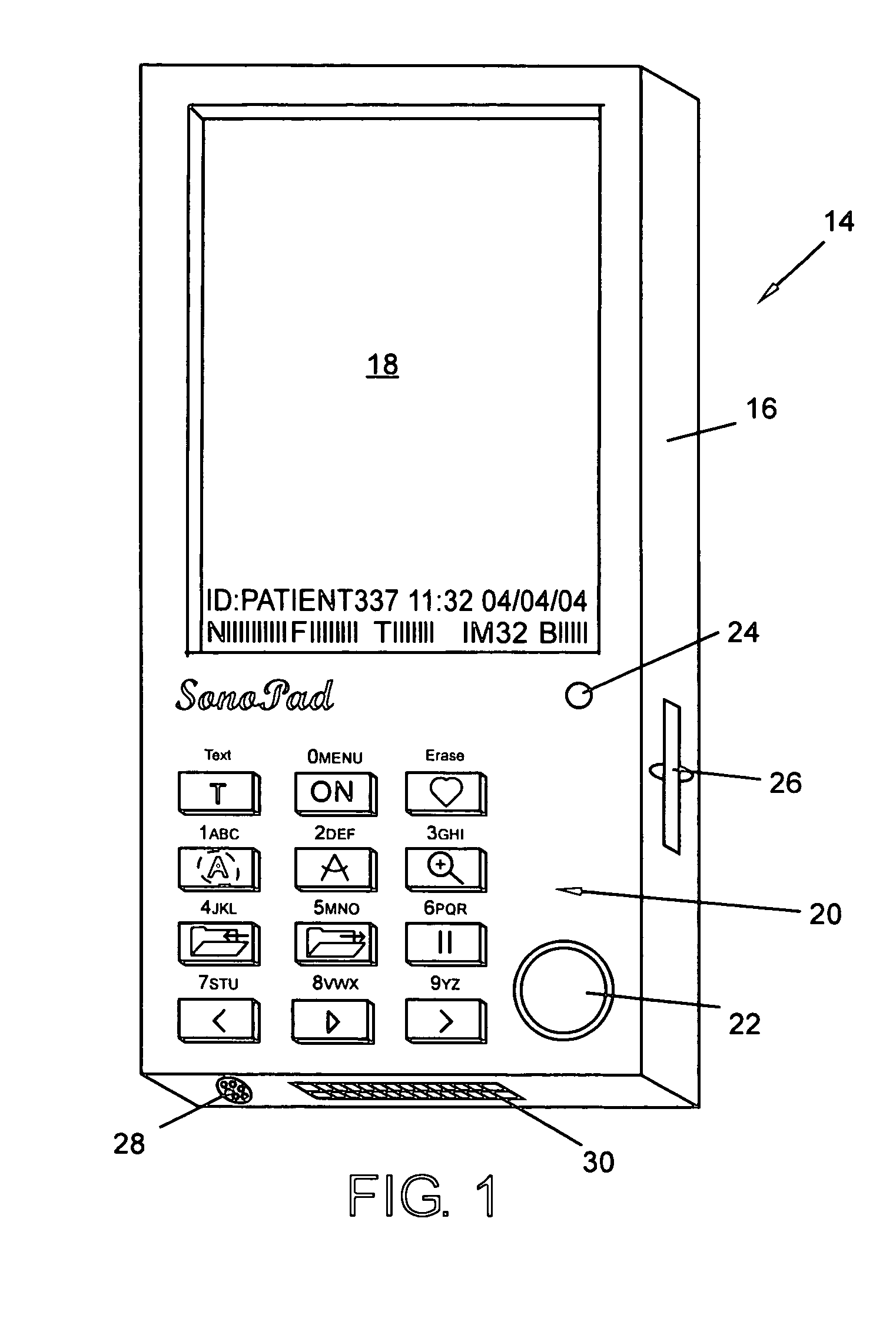
[0065]FIG. 2 is a perspective view of a key_pad in accordance with the present invention.

[0066]FIG. 3 is a perspective bottom view of a diagnostic_ultrasound_device in accordance with the present invention.

[0067]FIG. 4 is a complete system view of a diagnostic_ultrasound_device in accordance with the present invention.

[0068]FIG. 5 is an application view of a diagnostic_ultrasound_device in accordance with the present invention.

[0069]FIG. 6 is an application view of a diagnostic_ultrasound_device in accordance with the present invention.

[0070]FIG. 7 is a perspective view of a head_mounted_display (HMD) of the diagnostic_ultrasound_device in accordance with the present invention.

[0071]FIG. 8 is a block diagram view of a diagnostic_ultrasound_device in accordance with the present invention.

[0072]FIG. 9 is a block diagram view of a dual-core_processor in accordance w...


PUM


Abstract

A handheld diagnostic ultrasound device is disclosed which is pocket sized, lightweight and is designed for clear imaging under adverse lighting conditions by utilizing a custom Head Mounted Display (HMD). The handheld diagnostic ultrasound device comprises a removable probe and a removable HMD that connects to the personal digital assistant (PDA) style control unit. The handheld diagnostic ultrasound device may be viewed on the VGA LCD Display on the diagnostic ultrasound device or on the HMD. Images obtained may be stored to a secure digital flash or transferred via USB (Universal Serial Bus) or wireless link to a remote computer system for further processing or archiving. The handheld diagnostic ultrasound device is based on a dual-core processor that achieves a level of integration not previously attainable in a handheld diagnostic ultrasound device.

Description

RELATED APPLICATIONS [0001] The present application is related to U.S. Pat. No. 6,641,533, issued Nov. 4, 2003, for HANDHELD PERSONAL DATA ASSISTANT (PDA) WITH A MEDICAL DEVICE AND METHOD OF USING THE SAME, by Causey, III et al., included by reference herein. [0002] The present application is related to U.S. Pat. No. 6,569,102, issued May 27, 2003, for MINIATURIZED ULTRASOUND APARATUS AND METHOD, by Imran et al., included by reference herein. [0003] The present application is related to U.S. Pat. No. 6,569,101, issued May 27, 2003, for MEDICAL DIAGNOSTIC ULTRASOUND INSTRUMENT WITH ECG MODULE, AUTHORIZATION MECHANISM AND METHODS OF USE, by Quistgaard et al., included by reference herein. [0004] The present application is related to U.S. Pat. No. 6,540,685, issued Apr. 1, 2003, for ULTRASONIC DIAGNOSTIC DEVICE, by Rhoads et al., included by reference herein. [0005] The present application is related to U.S. Pat. No. 6,540,682, issued Apr. 1, 2003, for PORTABLE, CONFIGURABLE AND SCALAB...

Claims


Application Information

Patent Timeline
IPC IPC(8): A61B8/00A61B8/08
CPCA61B8/08A61B8/0833A61B8/565A61B8/467A61B8/488A61B8/462A61B8/4227A61B8/4427
Inventor NEFOS, THOMAS P.
Owner SONOPAD
Why Eureka
Try Eureka