Solid immersion lens, condensing lens, optical pickup device, optical recording and reproducing apparatus and method of forming solid immersion lens

a technology of solid immersion lens and optical pickup device, which is applied in the direction of lenses, instruments, record information storage, etc., can solve the problems of difficult to obtain a solid immersion lens with a large numerical aperture, unavoidable shape limitation of the condensing lens, and small tilt margin, etc., to achieve the effect of large numerical aperture, easy to obtain and maximum numerical apertur

Inactive Publication Date: 2005-10-20
SONY CORP
View PDF11 Cites 25 Cited by
  • Summary
  • Abstract
  • Description
  • Claims
  • Application Information

AI Technical Summary

Benefits of technology

[0046] Also, according to the method for forming the solid immersion lens of the present invention, since this forming method comprises at least the process for forming the inclined portion on the lens material body, the process for forming the convex portion on the objective side of the lens material body and the process for processing the objective surface of the convex portion, when the inclined portion is formed by the machine process and the convex portion is formed by a suitable method such as the semiconductor process technology, the objective surface can be formed as the very small area as compared with the related art and hence the process time and process volume of this objective surface can be decreased.
[0047] Therefore, according to the solid immersion lens forming method of the present invention, it becomes possible to easily obtain the condensing lens in which the tilt margin between the objective surface and the optical recording medium can be increased and which has the large numerical aperture.
[0048] Further, in the solid immersion lens forming method of the present invention, when the convex portion of the solid immersion lens is processed as the shape which can satisfy the above-described equations (1) to (3), as described above, it is possible to form the solid immersion lens in which the tilt margin between the objective surface and the optical recording medium can be increased as compared with the related-art solid immersion lens and which can obtain the maximum numerical aperture.
[0049] Also, in the solid immersion lens forming method of the present invention, when the tip end portion of the convex portion is formed as the shape which substantially circumscribes the sphere with the diameter of approximately r if the spherical portion is the hemispherical portion or when it is formed as the shape which substantially circumscribes the sphere with the radius of approximately r / n if the spherical portion is the hyper-hemispherical portion, it is possible to form the solid immersion lens in which the tilt margin between it and the object such as the optical recording medium can be increased and in which the assembly accuracy margin with other optical lens can be increased.
[0050] Further, in the above-mentioned solid immersion lens forming method, when the tip end portion of the solid immersion lens is processed as the shape which can satisfy the above-described equations (1) to (3) and it is also processed as the shape which substantially circumscribes the sphere with the diameter of approximately r if the spherical portion is the hemispherical portion or it is also processed as the shape which substantially circumscribes the sphere with the radius of approximately if the spherical portion is the hyper-hemispherical portion, it is possible to easily form the solid immersion lens with the large numerical aperture in which the tilt margin between it and the object such as the optical recording medium can be increased and in which the assembly accuracy margin with other optical lens can be increased.
[0051] Furthermore, in the above-mentioned respective solid immersion lens forming methods, when the tip end portion of the convex portion is processed by the focus ion beam process method, it is possible to form the objective lens with the extremely small area reliably with high accuracy as compared with the related art.

Problems solved by technology

Also, since a diameter of a beam spot of focused light introduced into the condensing lens after it has been emitted from the light source is reduced and a distance between the optical recording medium and the condensing lens is extremely decreased to become less than about several tens of nanometers, an inclination margin between the optical recording medium and the condensing lens, that is, so-called tilt margin becomes very small, and it is unavoidable that the condensing lens is much restricted from a shape standpoint.
However, when the solid immersion lens in which the objective side is formed as the circular cone shape is formed, depending upon the inclination angle of the circular cone shape, it is difficult to obtain a solid immersion lens with a large numerical aperture or there is a risk that a holding member for holding the lens will not be bonded to the lens satisfactorily.
Further, when a very small flat surface is formed on a part of the objective surface of the lens processed as the circular cone shale by a microminiaturizing process means based on a semiconductor process technology such as an RIE (reactive ion etching), a complex process for masking the circular cone portion by using a photolithography becomes necessary and as a result, a problem arises, in which a process time is extended.
Further, also in this case, if the radius of curvature of the solid immersion lens is as large as about several millimeters, then a problem arises, in which the solid immersion lens is restricted by a tilt margin between the end portion of the objective surface and the optical recording medium.
However, when the radius of curvature of the solid immersion lens is made extremely small, for example, the radius of curvature is selected to be less than the radius of 0.5 mm, for example, a problem arises, in which it becomes more difficult to process, in particular, the tip end portion by the above-mentioned forming method.

Method used


Image

  • Solid immersion lens, condensing lens, optical pickup device, optical recording and reproducing apparatus and method of forming solid immersion lens
  • Solid immersion lens, condensing lens, optical pickup device, optical recording and reproducing apparatus and method of forming solid immersion lens
  • Solid immersion lens, condensing lens, optical pickup device, optical recording and reproducing apparatus and method of forming solid immersion lens

Examples


Embodiment Construction

[0101] The present invention will now be described in detail with reference to the drawings.

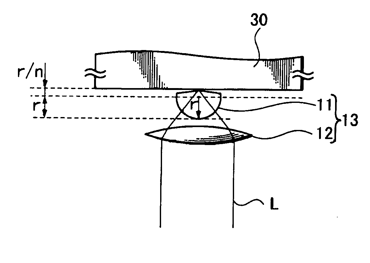
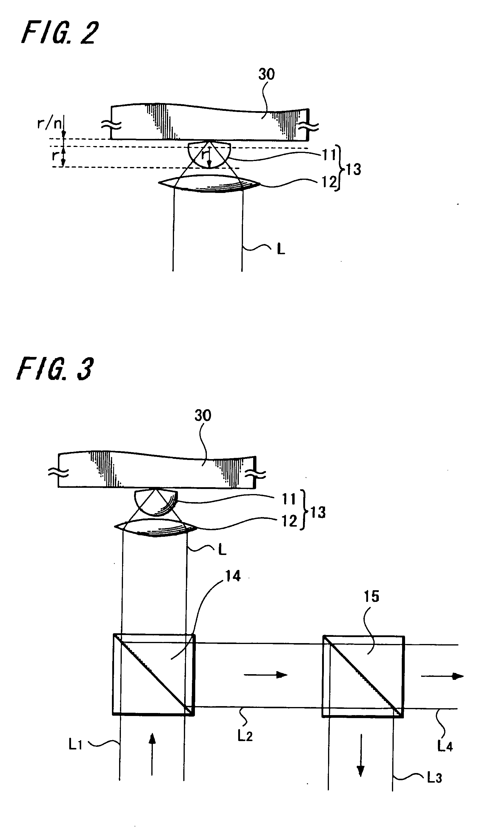
[0102] The present invention can be applied to a solid immersion lens and a manufacturing method thereof, a condensing lens comprising this solid immersion lens and an optical lens with its optical axis coincident with the solid immersion lens and which is located on the opposite side of an objective lens side. Further, the present invention can be applied to an optical pickup device including this condensing lens and which adopts a so-called near-field optical recording and reproducing system and an optical recording and reproducing apparatus including this optical pickup device.

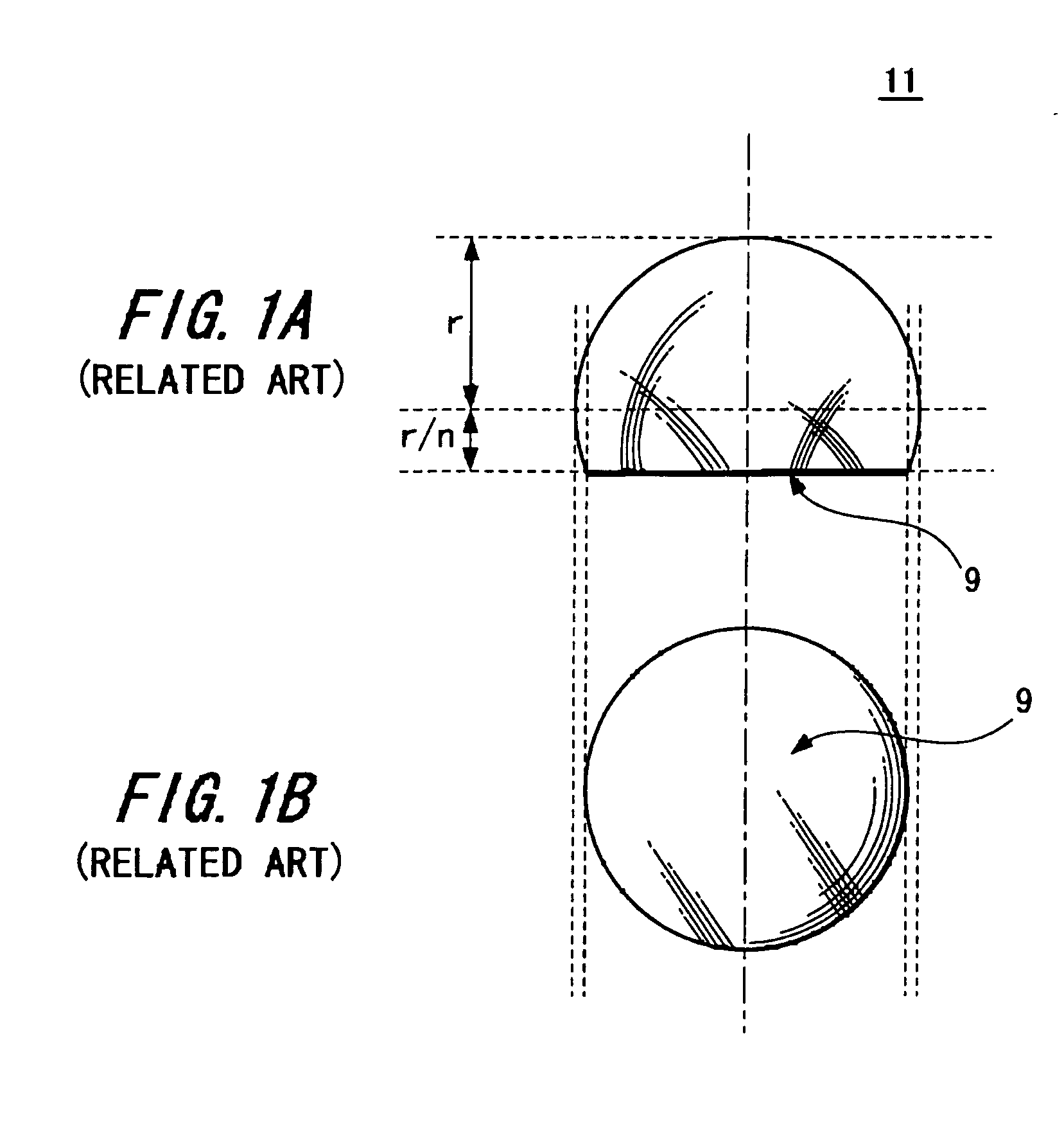
[0103] First, prior to the description of the solid immersion lens according to the present invention and a forming method thereof, embodiments in which the present invention was applied to the condensing lens, the optical pickup device and the optical recording and reproducing apparatus will be described with refe...


PUM

PropertyMeasurementUnit
oscillation wavelengthaaaaaaaaaa
diameteraaaaaaaaaa

Abstract

A solid immersion lens 11 has an inclined portion 4 formed on at least a part thereof from the tip end portion of the objective side to a spherical portion and an inclination angle θ is expressed as θ≧i where θi represents the angle of incidence of light incident on the solid immersion lens 11. There are provided a solid immersion lens capable of increasing a tilt margin between a lens and an optical recording medium and so on and which can decrease a diameter of a lens and a method for forming a solid immersion lens.

Description

CROSS REFERENCES TO RELATED APPLICATIONS [0001] The present invention contains subject matter related to Japanese Patent Application JP 2004-073162 and JP 2005-018662 filed in the Japanese Patent Office on Mar. 15, 2004 and Jan. 26, 2005 respectively, the entire contents of which being incorporated herein by reference. BACKGROUND OF THE INVENTION [0002] 1. Field of the Invention [0003] The present invention generally relates to a solid immersion lens (SIL), a condensing lens using such solid immersion lens, an optical pickup device, an optical recording and reproducing apparatus (or a magneto-optical recording and reproducing apparatus) and a method for forming a solid immersion lens. More particularly, this invention relates to a solid immersion lens, a condensing lens, an optical pickup device, an optical recording and reproducing apparatus and a method for forming a solid immersion lens suitable for use with a so-called near-field optical recording and reproducing system in which...

Claims


Application Information

Patent Timeline
Patent Type & Authority Applications(United States)
IPC IPC(8): G02B13/00G02B19/00G02B21/33G11B7/00G11B7/135G11B7/1374G11B7/1378G11B7/1387G11B7/22
CPCG02B21/33G11B7/1374G11B7/1378G02B19/0014G11B7/22G02B19/0085G02B19/0047G11B7/1387
Inventor SHINODA, MASATAKA
Owner SONY CORP
Why Eureka
Try Eureka