
Nonlinear method and apparatus for electrocardiogram pacemaker signal filtering

a technology of electrocardiogram and pacemaker, applied in the field of electrocardiogram (ecg) digital signal processing, can solve the problems of limiting the effectiveness of linear filtering techniques, adding significant cost and expense to the processing and storage of the increased flow rate and quantity of data, and not being able to meet the needs of pacer signal components

Inactive Publication Date: 2005-10-20
WELCH ALLYN INC
View PDF8 Cites 45 Cited by
  • Summary
  • Abstract
  • Description
  • Claims
  • Application Information

AI Technical Summary

Benefits of technology

[0006] The pacer filtering method and mechanism described herein effectively overcomes the above-noted limitations, operates under these “real world” conditions, and provides other benefits.
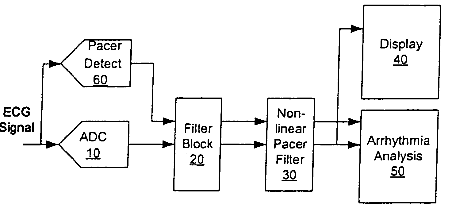
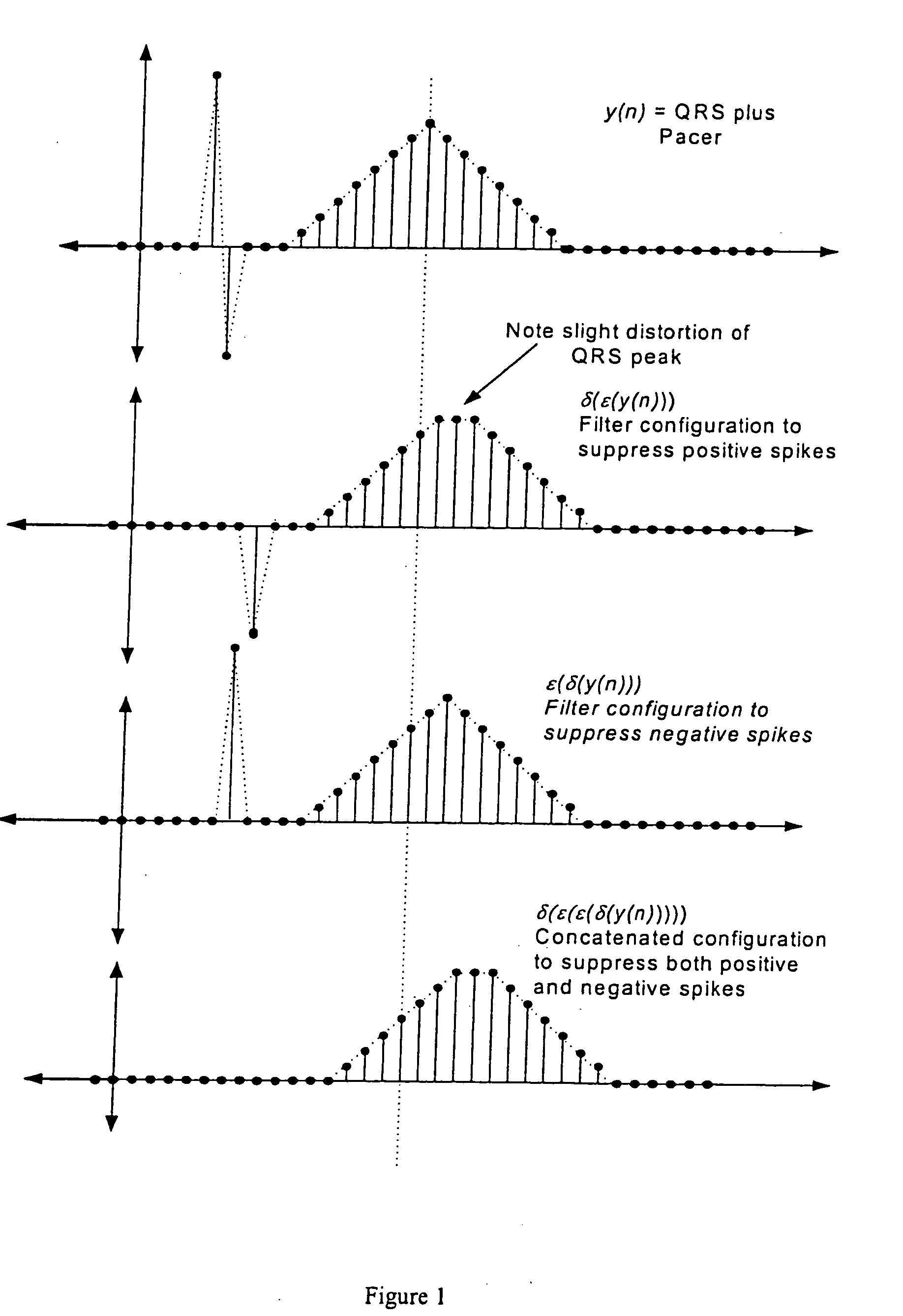
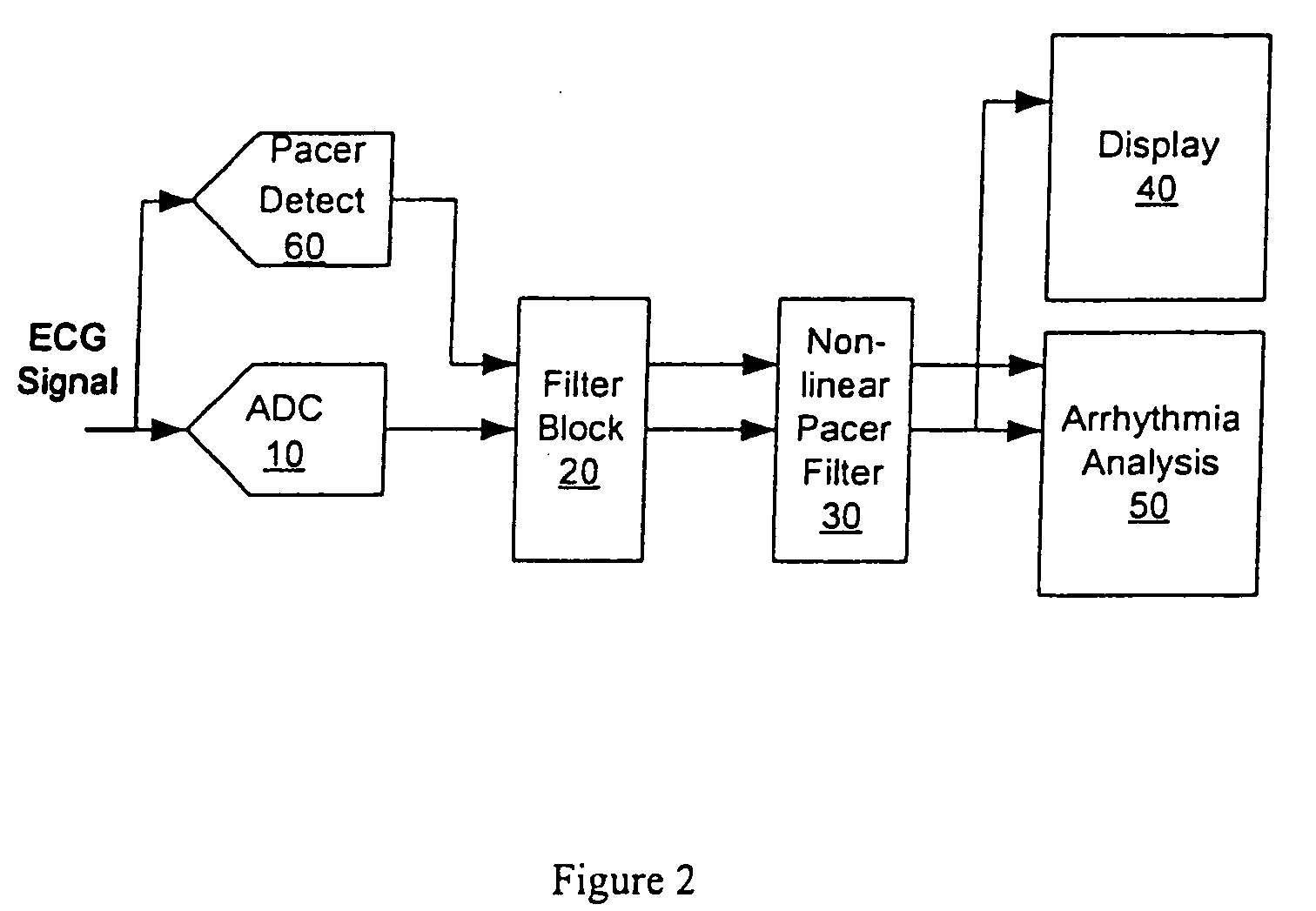
[0019] Morphological operators are used according to the present invention in order to remove “peaks” and “valleys” in an ECG signal whose widths are less than a specified threshold, without injecting significant distortion into peaks and valleys above the specified threshold. This capability is important because a (biphasic) pacer spike is a component of the ECG signal with a significantly narrower peak, valley, or peak / valley characteristic than any other component in the ECG signal. This key discriminating characteristic allows the method to succeed regardless of where the pacer spike is located in relation to the QRS complex. The above method also succeeds regardless of the relative amplitudes of the peaks / valleys, so a large pacer spike is not a problem. In addition, no explicit signal is needed in order to flag the exact or approximate location of the pacer spike, as is required by other methods.
[0021] Although the morphological operators will not cause significant distortion to other components of the QRS complex, they can cause minor rounding of the tips of the wider peaks and valleys of the QRS complex. In order to avoid this noted effect, a further aspect of the herein described method and apparatus is the ability to switch dynamically in real-time between a linear input-to-output delay operator and the above-noted morphological operators. The switch is free of transient response effects, extra delays, distortion, and / or loss of data. Given a separate external signal to flag the presence of a pacer signal spike, or by using the morphological operators to automatically detect the spike, the morphological operators generate the output samples in the proximity of the pacer spike. Outside of this proximity, the linear operator generates the output samples distortion-free. The input-output delay of the linear filter should preferably be set to match the input-output delay of the morphological operators.
[0022] It may sometimes be beneficial to always filter using the morphological operators (and not switch dynamically to the linear delay operator). For example, these operators provide an added benefit of removing impulsive noise sources (narrow noise spikes corrupting the ECG signal) that may be present in some environments.

Problems solved by technology

If a pacemaker (pacer) signal is added to the ECG signal, this sampling rate is no longer adequate for the pacer signal component because a significant portion of its energy is at frequencies greater than 250 Hz.
Increasing the sampling rate in order to accommodate the pacer signal component would add significant cost and expense to all devices and systems processing and storing the increased flow rate and quantity of data.
This fundamentally limits the effectiveness of linear filtering techniques, even at higher sampling rates.
Other practical challenges are that the signal can: (a) range in amplitude from a fraction of the QRS amplitude to 100 times larger, (b) have significant undershoot or overshoot (e.g., biphasic), and (c) have a relatively long (e.g., >40 ms) settling time.
Poorly removing the signal, on the other hand, could increase the probability of additional analysis error.

Method used


Image

  • Nonlinear method and apparatus for electrocardiogram pacemaker signal filtering
  • Nonlinear method and apparatus for electrocardiogram pacemaker signal filtering
  • Nonlinear method and apparatus for electrocardiogram pacemaker signal filtering

Examples


Embodiment Construction

[0042] It is commonly known that characteristics of a typical ECG signal include a periodic repetition of sequential pulses or “waves” labeled “P”, “Q”, “R”, “S” and “T” each associated with stages of the heart's periodic electrical depolarization and re-polarization that controls its pumping action. The Q, R, and S pulses are contiguous and form the “QRS complex”, in which the R wave is dominant. The Q and S pulses are often indistinguishable from the noise floor.

[0043] In ECG signals over the range of patients covering neonatal to adult, these pulses have the following typical duration and amplitude characteristics.

Pulse NameDuration (ms)Amplitude (mV)P20 to 100±0.0 to ±0.3QRS20 to 120±0.5 to ±5.0T20 to 120±0.2 to ±1.2

The preceding pulse dimensions are in sharp contrast with that of a typical pacemaker signal pulse that ranges in amplitude from approximately ±2 mV to ±700 mV and in duration from about 0.1 ms to 2 ms. Because the pacer signal spike is so much shorter in duratio...


PUM


Abstract

Signal “peak” and “valley” removal properties of mathematical morphology operators are exploited in a method and apparatus for detecting, removing, or improving fidelity of pacemaker signal components of the Electrocardiogram (ECG) at sampling rates well below the pacemaker signal Nyquist rate. The method works for the wide variability in pacemaker signal amplitude, width, firing frequency, and other characteristics encountered in practice, and it works for malfunctioning pacemakers that may fire at any point relative to the QRS complex of the ECG signal. Filtering operations require minimal digital storage and are computationally inexpensive (no multiplications), mainly involving “maximum” and “minimum” type signal detections over a finite time history of the input signal. This implies that the method can be inexpensively implemented on small instruments in either hardware or software. The method may also be used to estimate the height and polarity of the pacemaker voltage spike, even though the base sampling period may be longer than the width of the spike.

Description

CROSS REFERENCE TO RELATED APPLICATION [0001] This application is based upon a provisional patent application, U.S. Ser. No. 60 / 560,677, filed Apr. 8, 2004, under 35 USC §119(e), the entire contents of which are herein incorporated by reference.FIELD OF THE INVENTION [0002] The invention relates to the field of electrocardiogram (ECG) digital signal processing, and more specifically to the application of digital filtering as used in order to improve ECG signal qualities for automated machine analysis and / or human interpretation. BACKGROUND OF THE INVENTION [0003] Because the ECG signal bandwidth typically observed for clinical diagnosis is less than 75 Hz, sampling rates that range between 150 and 500 Hz are sufficient to support clinical interpretation or automated machine analysis. If a pacemaker (pacer) signal is added to the ECG signal, this sampling rate is no longer adequate for the pacer signal component because a significant portion of its energy is at frequencies greater th...

Claims


Application Information

Patent Timeline
IPC IPC(8): A61B5/308A61N1/362A61N1/37G06F17/00H03H17/02
CPCA61N1/3704A61B5/0452A61B5/349A61B5/366
Inventor HOLLAND, ALEXANDER
Owner WELCH ALLYN INC
Learn More