
Method and apparatus for making positive electrode films for polymer batteries

a technology of positive electrode material and polymer battery, which is applied in the field of polymer batteries, can solve the problems of inefficient process for mass production of cathode material, reduced density, and difficulty in extruding positive electrode material into thin films, and achieves high solid conten

Inactive Publication Date: 2005-10-27
BATHIUM CANADA
View PDF7 Cites 41 Cited by
  • Summary
  • Abstract
  • Description
  • Claims
  • Application Information

AI Technical Summary

Benefits of technology

"The invention provides a method and apparatus for manufacturing a composite positive electrode film with a high solid content and a low thickness. The method involves compounding an active cathode material, an electronically conductive additive, and an ionically conductive polymer electrolyte in an extruder and extruding it through a sheet die to obtain a film with a thickness of more than 50 μm. The film is then reduced in thickness by using a pair of nip rollers or a series of at least two pairs of nip rollers. The apparatus includes a belt, a dispenser for lubricant, and a plurality of nip rollers with progressively smaller nip distance. The invention allows for the production of a thin and high-solid content positive electrode film with good adhesion and performance."

Problems solved by technology

This process is inefficient for the mass production of cathode films since it requires recycling the. solvent evaporated and the resulting cathode films have a relatively high porosity, and therefore decreased density.
However, the extrusion of positive electrode material into thin films is rendered extremely difficult by the high percentage of solids (active material and conductive filler) necessary to produce high energy density cathode films.
The difficulty increases dramatically when attempting to directly extrude cathode films of less than 50 μm.
The pressure required to extrude cathode material with over 40% solid content through a sheet die opening of less than 50 μm is such that the die itself may not resist and a gear pump capable of generating the required pressure may not be available on the market and therefore must be custom built.
Unfortunately, it is extremely difficult to process through an extruder cathode materials having a high solid content of active cathodic material and conductive filler (above 30%) to form a thin positive electrode composite film of less than 50 μm and preferably less than 30 μm.

Method used


Image

  • Method and apparatus for making positive electrode films for polymer batteries
  • Method and apparatus for making positive electrode films for polymer batteries
  • Method and apparatus for making positive electrode films for polymer batteries

Examples


second embodiment

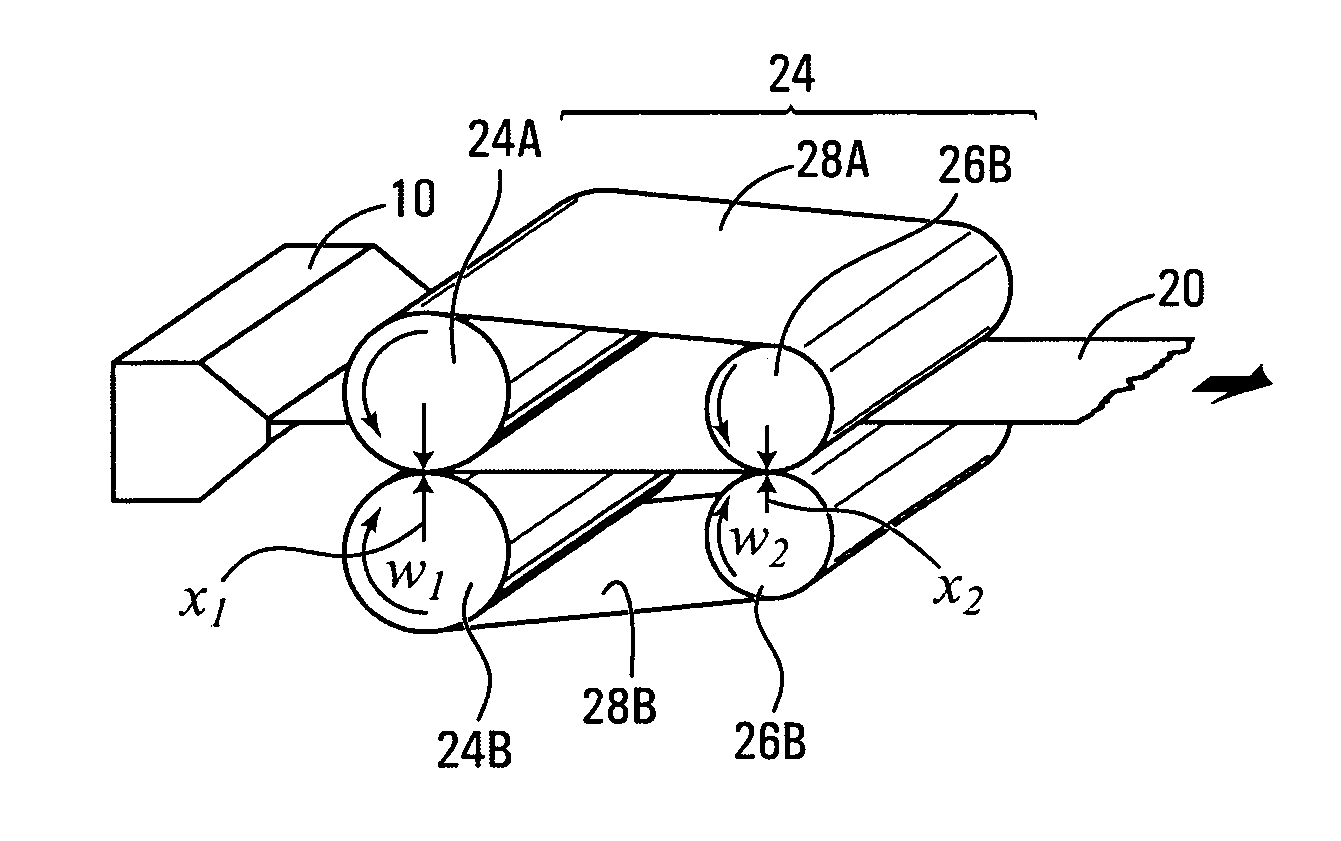
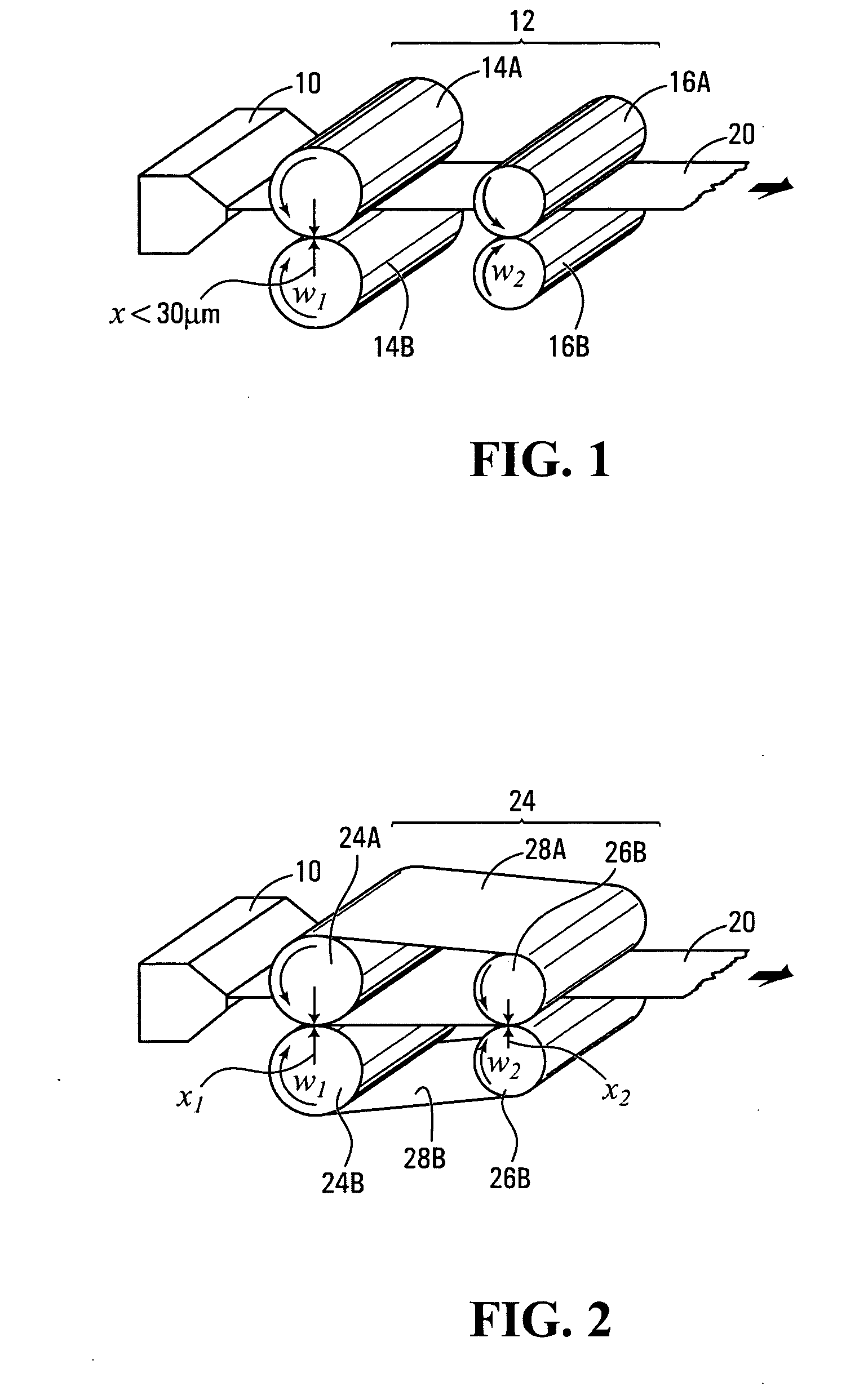
[0041] In FIG. 2, there is shown the invention in which a calendering apparatus 22 is juxtaposed to a sheet die 10 of a typical single or twin screw extruding machine (not shown). Calendering apparatus 22 comprises a first pair of cylindrical nip rollers 24A and 24B and a second pair of cylindrical nip rollers 26A and 26B. In this specific embodiment, nip rollers 24A and 26A are joined by a metallic belt 28A that remains in contact with the composite positive electrode sheet 20 as it is being calendered. Similarly, nip rollers 24B and 26B are joined by a metallic belt 28B that remains in contact with the composite positive electrode sheet 20 as it is being calendered. The metallic belts 28A and 28B impose that the rotational speeds of nip rollers 24A and 26A and of nip rollers 24B and 26B are equal such that ω1=ω2.

[0042] In one example of implementation, the distance x1 between nip rollers 24A and 24B is set at the final desired thickness of composite positive electrode sheet 20 of ...

third embodiment

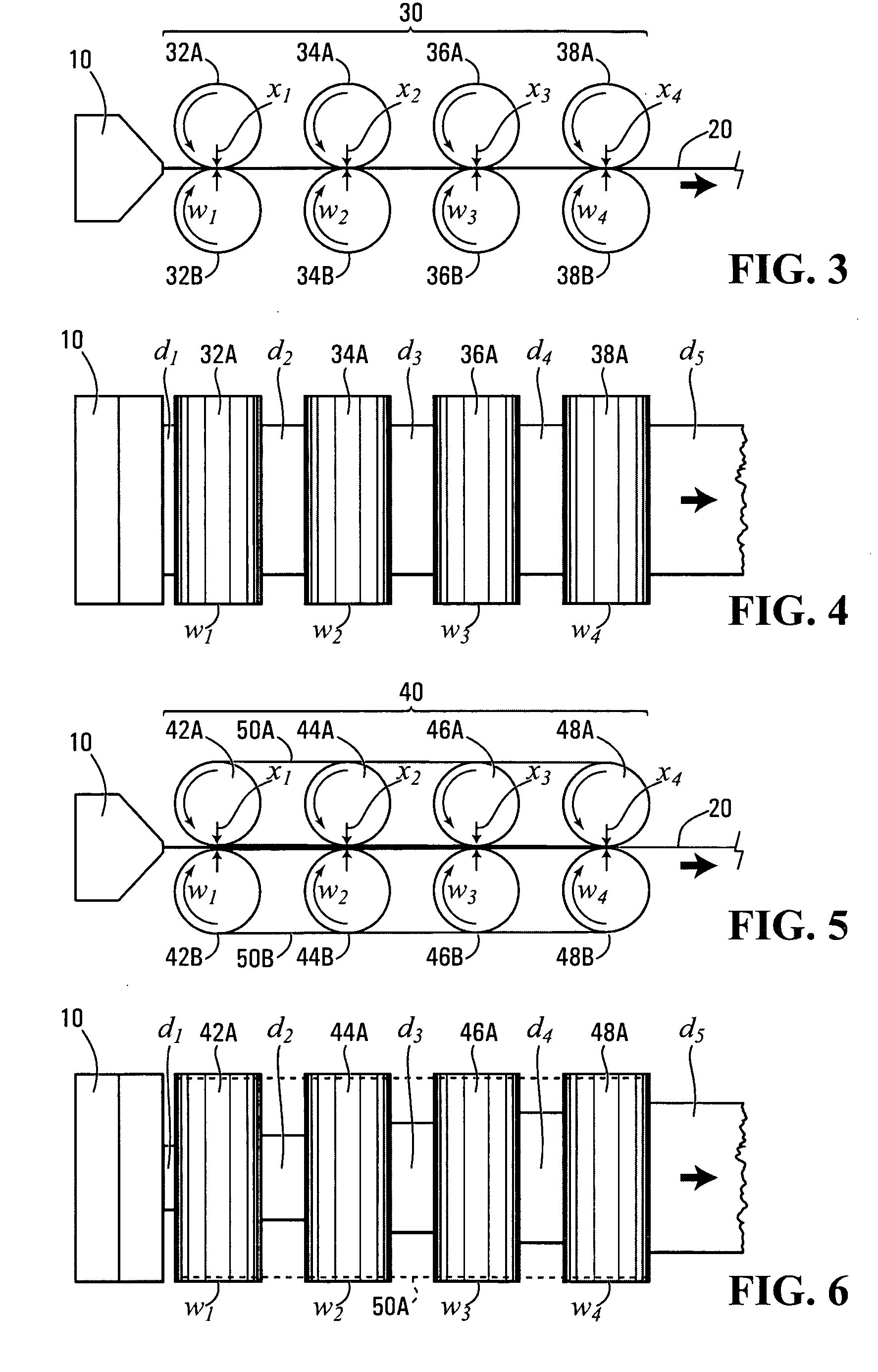
[0046] In FIGS. 3 and 4, there is shown respectively a side elevational view and a top plan view of the invention in which a calendering apparatus 30 is juxtaposed to a sheet die 10 of a typical single or twin screw extruding machine (not shown). Calendering apparatus 30 comprises a series of cylindrical nip rollers 32A, 32B, 34A, 34B, 36A, 36B, 38A and 38B arranged in pairs and adapted to progressively reduce the thickness of a composite positive electrode sheet 20 passing through the calendering apparatus 30. In this embodiment, the distances x1, x2 and x3 between the nip rollers 32A and 32B, 34A and 34B, and 36A and 36B, respectively, gradually decrease such that x1>x2>x3 and the thickness reduction, work performed on the composite positive electrode sheet 20 is also more gradual than in the previous embodiments shown in FIGS. 1 and 2. As an example only, the composite positive electrode sheet 20 may exit die 10 at a thickness of 75 μm, the distances x1, x2 and x3 between the nip...

fourth embodiment

[0049] In FIGS. 5 and 6, there is shown respectively a side elevational view and a top plan view of the invention in which a calendering apparatus 40 is juxtaposed to a sheet die 10 of a typical single or twin screw extruding machine (not shown). Calendering apparatus 40 comprises a series of pairs of cylindrical nip rollers 42A-42B, 44A-44B, 46A-46B, and 48A-48B, as well as two metallic belts 50A and 50B respectively circumscribing and joining together the two banks of nip rollers 42A-44A-46A-48A and 42B-44B-46B-48B. Calendering apparatus 40 is adapted to progressively reduce the thickness of a composite positive electrode sheet 20 passing through the calendering apparatus 40. In this embodiment, the distances x1, x2 and x3 between the nip rollers 42A and 42B, 44A and 44B, and 46A and 46B, respectively, gradually decrease such that x1>x2>x3 and the thickness reduction work performed on the composite positive electrode sheet 20 is also more gradual than in the previous embodiments s...


PUM

PropertyMeasurementUnit
thicknessaaaaaaaaaa
thicknessaaaaaaaaaa
thicknessaaaaaaaaaa

Abstract

A method and an apparatus for manufacturing through an extruder a composite positive electrode film having a thickness of less than 50 μm and having a high solid content.

Description

CROSS-REFERENCE TO RELATED APPLICATION [0001] The present application claims priority from U.S. provisional application No. 60 / 535,828 filed on Jan. 13, 2004.FIELD OF THE INVENTION [0002] The present invention relates generally to polymer batteries and, more specifically, to a method and an apparatus for making positive electrode films for polymer batteries. BACKGROUND [0003] Rechargeable batteries manufactured from laminates of polymer electrolytes and sheet-like electrodes display many advantages over conventional liquid electrolyte batteries. These advantages include lower overall battery weight, high power density, high specific energy, and longer service life. In addition, they are more environmentally friendly since the danger of spilling toxic liquid into the environment is eliminated. [0004] Polymer battery components generally include positive electrodes (also referred to as cathodes), negative electrodes (also referred to as anodes), and an insulating material capable of p...

Claims


Application Information

Patent Timeline
Patent Type & Authority Applications(United States)
IPC IPC(8): B29C48/08B29C55/18D01D5/16H01M4/131H01M4/1391H01M10/0525
CPCB29C43/22B29C47/0021B29C47/885B29C47/886B29C55/18H01M4/0404Y02T10/7011H01M4/0435H01M4/131H01M4/1391H01M10/0525H01M2004/028H01M4/0411B29C48/08B29C48/914B29C48/9145B29C48/9155Y02E60/10
Inventor BROSCH, BERNDGAGNON, REGIS
Owner BATHIUM CANADA
Learn More