Method for machine tool and profilometer coordinate registration

a technology of profilometer and machine tool, applied in the field of profilometer measurements, can solve the problems of directing the machine to address a specific measured point on the workpiece, erratic electric current,

Inactive Publication Date: 2005-10-27
EASTMAN KODAK CO
View PDF14 Cites 4 Cited by
  • Summary
  • Abstract
  • Description
  • Claims
  • Application Information

AI Technical Summary

Benefits of technology

[0007] The method provides a means for registering measured surface data with commanded machining actions in all three degrees of freedom required to define surface points. An advantage of the method is that it may be used even when the shape of the machined cut volume is complex or even impossible to predict. This is often the case for polishing processes and other processes that use flexible tools. The method is not sensitive to cut volume errors that may result from cutter deflection, etc., as long as the cut process is consistent, even when rigid tools are used.

Problems solved by technology

Directing the machine to address a specific measured point on the workpiece is problematic because it is necessary to identify both the relative position and orientation of the measurement data with respect to the machine tool coordinate system.
Electric currents can be erratic due to resistance changes in the electric current path, such as can occur between different workpieces or the same workpiece at different times.

Method used


Image

  • Method for machine tool and profilometer coordinate registration
  • Method for machine tool and profilometer coordinate registration
  • Method for machine tool and profilometer coordinate registration

Examples


Embodiment Construction

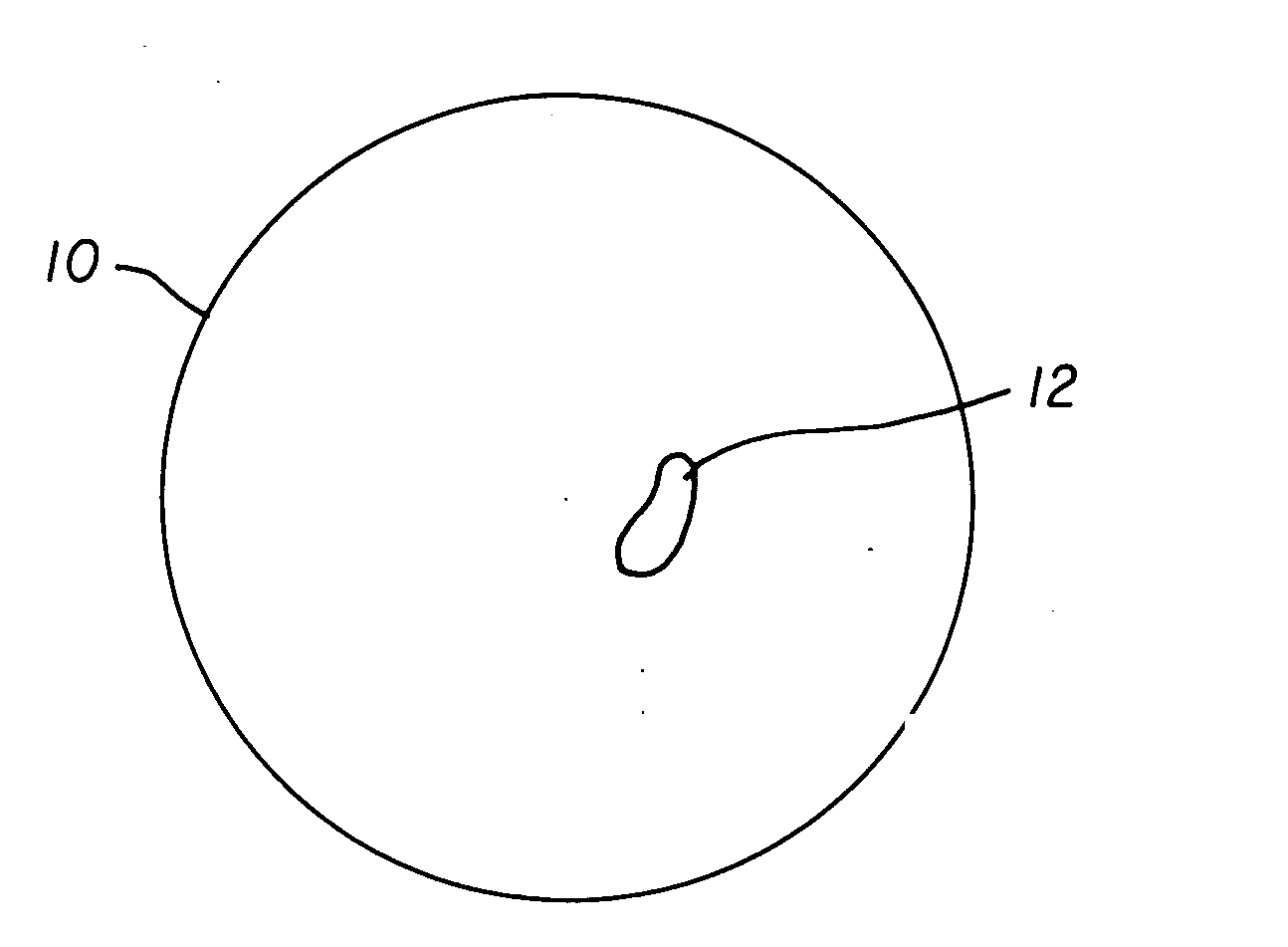
[0016] Referring to FIG. 1, an example of a process for a machine tool that executes a material removal process that is difficult to characterize is polishing with a spinning compliant tool. The material removed depends on the shape of the contact area between the tool and the work-piece 10, the pressure distribution across this contact area, and dynamic effects such as fluid flow and fluid layer thickness. Because of these variables, it is difficult to predict the material removal area and volume.

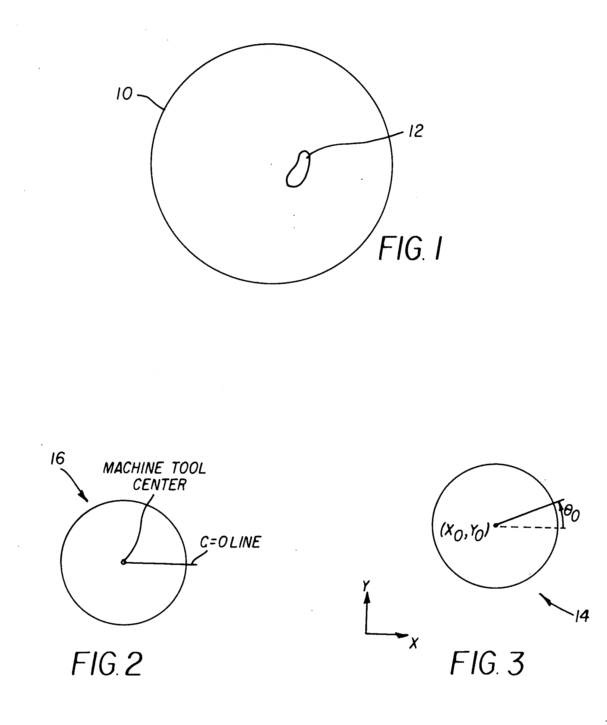
[0017] If the polishing tool is held in a fixed position for some period of time, the resulting polished area 12 has an irregular shape. The way current machines are used is to measure the current surface of an optic, plan a polishing action to correct errors, and then execute the polishing plan on the machine. This requires correlating the coordinate system of the measurement machine with the coordinate system of the polishing machine.

[0018] Referring to FIGS. 2 and 3, a profilometer 14...


PUM


Abstract

A method for registering machine tool and profilometer coordinates, wherein the machine tool defines a C-axis having a zero position, C=0, comprises loading a sacrificial workpiece into the machine tool; cutting several first features in a surface of the sacrificial workpiece and producing a linear machine tool motion across the workpiece; determining the centroid of each first cut feature; fitting a line to the centroids of the first cut features; and measuring angle θ0 of the line relative to the C-axis zero position. The angle θ0 is the departure in profilometer coordinates from the C=0 line. The method includes moving the machine tool to a fixed radius; cutting several second features in a surface of the sacrificial workpiece and producing a circular machine tool motion across the workpiece; determining the centroid of each second cut feature; fitting a circle to the centroids of the second cut features; and determining a center of the circle. The center of the circle is the machine tool center in profilometer coordinates.

Description

FIELD OF THE INVENTION [0001] The invention relates generally to profilometer measurements, and more particularly to a method for machine tool and profilometer coordinate registration. BACKGROUND OF THE INVENTION [0002] When machining precise surfaces of a workpiece, it is often necessary to measure them using a precise measuring instrument, such as a scanning profilometer. In these situations, it is necessary to register the measurements of the profilometer with the motion coordinates of the machine tool. A fixture is used to hold the workpiece while allowing the workpiece to be removed and replaced in the machine tool and profilometer in a repeatable fashion. For example, mounting the workpiece in the fixture allows it to be installed in the machine tool, removed and re-installed, and the position of the workpiece relative to the machine tool coordinate system will be identical to the original position. [0003] Consider a turning machine, for example, which has a controllable spind...

Claims


Application Information

Patent Timeline
Patent Type & Authority Applications(United States)
IPC IPC(8): G05B19/401G06F19/00
CPCG05B19/401G05B2219/50074G05B2219/37069
Inventor BROST, RANDOLPH C.STRIP, DAVID R.WILSON, RANDALL H.
Owner EASTMAN KODAK CO
Why Eureka
Try Eureka