Plasma torch for microwave induced plasmas

a plasma torch and microwave-induced technology, applied in the field of plasma torch for microwave-induced plasma, can solve the problems of significantly inferior to icp system, less well-developed micro-ionization plasma (mip) spectrometry, and less well-developed icp system analytical performance, etc., to avoid or avoid sensitivity degradation, slow down the effect of degrading

Inactive Publication Date: 2005-11-03
VARIAN AUSTRALIA PTY LTD
View PDF5 Cites 30 Cited by
  • Summary
  • Abstract
  • Description
  • Claims
  • Application Information

AI Technical Summary

Benefits of technology

[0024] Another problem encountered in torches for both ICP and MIP, particularly for samples that contain high total dissolved solids (TDS), is that radiated energy from the plasma heats up the outlet end of the inner (that is, the sample injection) tube and can lead to blockage of that tube. That is, a small portion of the liquid droplets in a nebulised sample travelling through the sample injection tube inevitably contact the inner surface of the tube and tend to adhere thereto and are dried by the heated tube. The solid component of such droplets remains attached to the inner surface and this deposit slowly builds up progressively occluding the inner (sample injection) tube near or at its outlet opening. The effect is a slowly degrading signal, with the sensitivity becoming progressively worse. This is particularly a problem for a microwave induced plasma torch if the sample injection (inner) tube is extended to be closer to the microwave induced plasma and / or has a relatively smaller outlet opening, as described hereinbefore.
[0025] Another aspect of the invention seeks to avoid or at least reduce this blockage problem when aspirating samples containing high TDS.

Problems solved by technology

Microwave induced plasma (MIP) spectrometry, however, is less well developed than ICP spectrometry, despite offering advantages, for example the availability of low cost, rugged and reliable microwave generators in the form of magnetrons.
This is because the analytical performance of MIP systems has, until a recent development of the applicant, been significantly inferior to ICP systems.
The inferior performance of MIP systems is due in large measure to the microwave induced plasma having different characteristics to a radio frequency ICP.
These characteristics of a microwave induced plasma make the plasma more difficult to confine such that a torch as usually used for ICP spectrometry is generally not suitable for MIP spectrometry.

Method used


Image

  • Plasma torch for microwave induced plasmas
  • Plasma torch for microwave induced plasmas
  • Plasma torch for microwave induced plasmas

Examples


Embodiment Construction

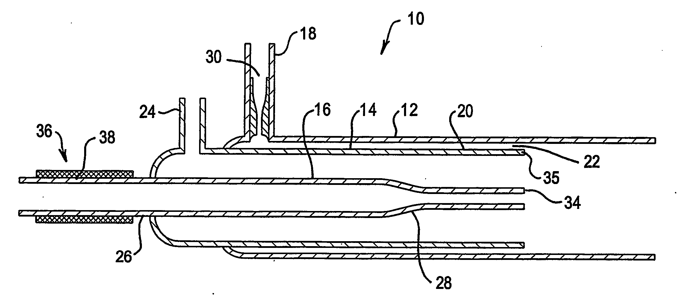
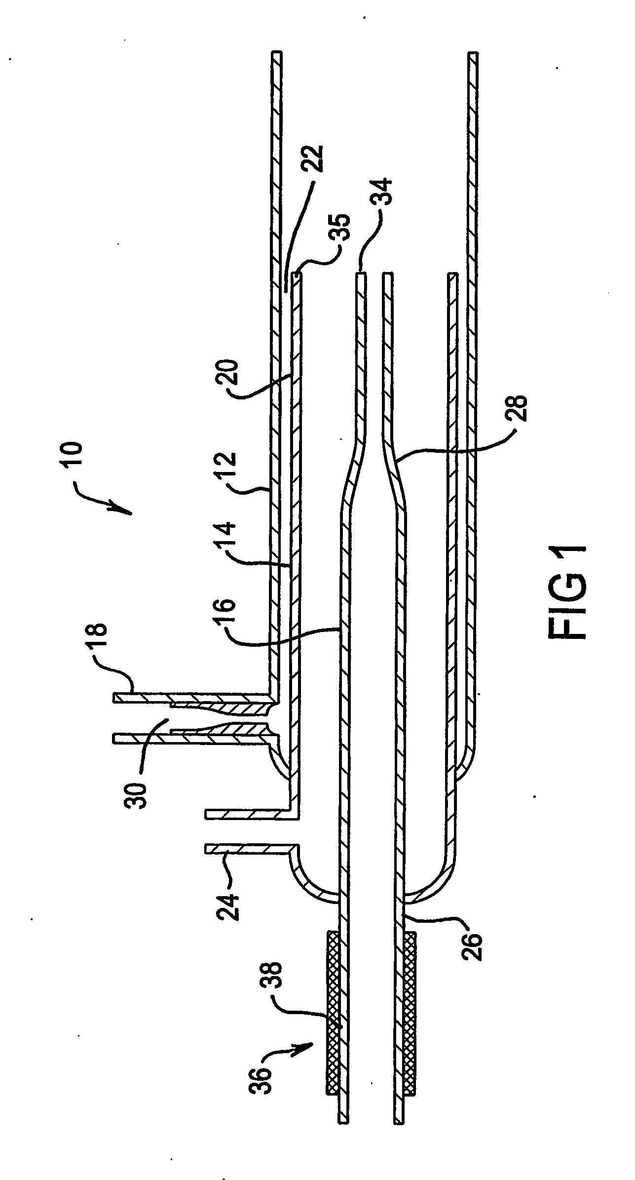
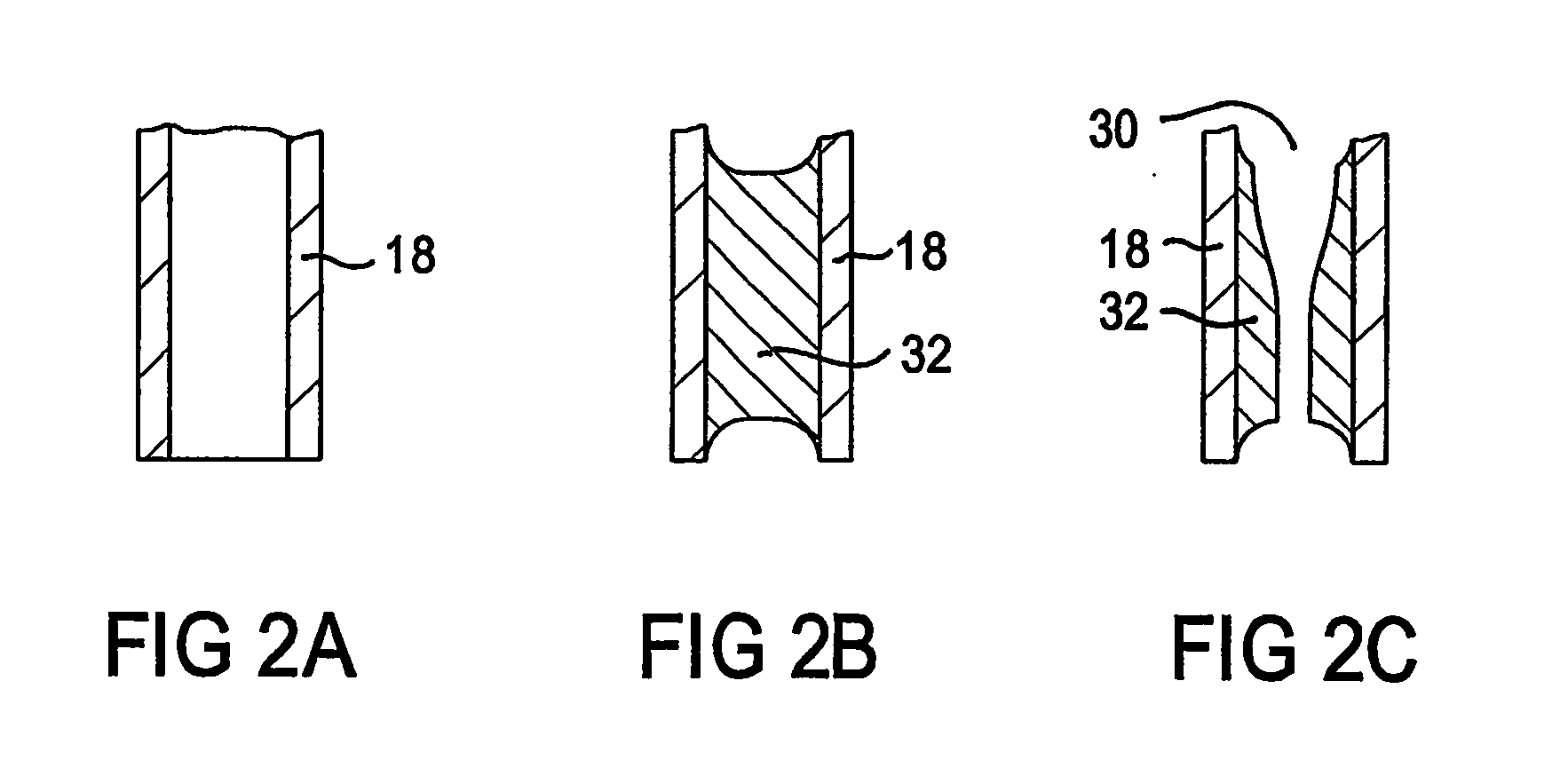
[0039] A microwave induced plasma torch 10 according to an embodiment of the invention comprises three concentric tubes, typically of quartz, namely an outer tube 12, an intermediate tube 14 and an inner tube 16. The outer tube 12 includes an outer-gas inlet 18 for supplying a gas flow (hereinbefore “a third gas flow”) between the outer tube 12 and the intermediate tube 14. The intermediate tube 14 has an end section 20 which together with the outer tube 12 defines an annular gap 22 for passage of the third gas. The third gas flow between the outer and intermediate tubes 12 and 14 (termed the main flow or plasma support gas flow) establishes a sheathing gas layer for a microwave induced plasma produced in the torch which separates the microwave induced plasma from the inner surface of the quartz outer tube 12 and thus stops this tube from melting. The outer-gas inlet 18 is arranged for the gas to be injected offset from the centre line of the torch such that the flow spirals or spin...


PUM

PropertyMeasurementUnit
frequencyaaaaaaaaaa
frequencyaaaaaaaaaa
pressureaaaaaaaaaa

Abstract

A Plasma torch (10) for microwave induced plasma spectrochemical analysis of a sample includes a nozzle (30) in an inlet (18) for the main plasma gas flow between outer tube (12) and intermediate tube (14) of the torch (10). The nozzle (30) increases the gas flow velocity in the sheathing gas layer for the plasma which is provided by the gas flow from the annular gap (22) between the tubes (12 and 14). The increased velocity of the gas in the sheathing gas layer “stiffens” that layer and thus better confines the microwave induced plasma (such better confinement not being necessary for an ICP torch). Thus the torch is of improved durability for a microwave induced plasma compared to an ICP torch. The sample injection (inner) tube (16) may have a reduced diameter outlet at its end (34) which is substantially level with the end (35) of intermediate tube (14) to improve injection of a sample into the microwave induced plasma. The inlet end (26) of the sample injection tube (16) may include a heater (36) to assist in preventing blockages in tube (16) near its outlet end.

Description

TECHNICAL FIELD [0001] The present invention relates to a torch for plasma spectrochemical analysis, in particular a microwave induced plasma (MIP)torch. BACKGROUND [0002] It is known that a plasma for spectrochemical analysis, for example for the elemental analysis of liquid samples, can be electrically excited, for example with radio frequency energy or microwave energy. Plasmas that are excited by radio frequency energy, that is, inductively coupled plasmas (ICP), are now well developed. In ICP spectrometry, the plasma is formed in a torch by induction from a surrounding coil excited with radio frequency energy, typically at between 20 and 50 MHz. The plasma forms as a hollow cylinder allowing injection of sample into the hollow central core of the plasma. Acceptable performance of ICP spectrometry requires close control of the gas flow regime including a sheathing gas flow around the plasma. In a typical ICP torch, regulation of the gas flows is ensured by a separate and indepen...

Claims


Application Information

Patent Timeline
Patent Type & Authority Applications(United States)
IPC IPC(8): G01N21/73G01N22/00G01N33/18H05H1/24H05H1/30
CPCG01N21/73H05H1/24G01N33/18G01N22/00H05H1/0031H05H1/30H05H1/3405H05H1/42
Inventor HAMMER, MICHAEL R.
Owner VARIAN AUSTRALIA PTY LTD
Why Eureka
Try Eureka