Synchronous machine design and manufacturing

a synchronous machine and synchronous motor technology, applied in the direction of windings, propulsion systems, magnetic circuit shapes/forms/construction, etc., can solve the problems of inefficiency and high cost, inability to meet the needs of most variable speed applications, and degradation of other aspects of motor performance and/or manufacturing cost, so as to reduce cost, increase performance, and eliminate cogging forces

Active Publication Date: 2005-11-03
MAGNEMOTION INC
View PDF99 Cites 18 Cited by
  • Summary
  • Abstract
  • Description
  • Claims
  • Application Information

AI Technical Summary

Benefits of technology

[0010] The invention provides novel synchronous machines and methods of design and construction thereof, more particularly, for example, to increase performance and decrease cost based a variety of combinations of: (i) selection of magnet and winding-slot size to eliminate cogging forces, (ii) use a winding that consists of non-overlapping coils so as to simplify manufacture and allow deeper slots; (iii) omission of extensions on the pole tips so that prewound coils can be inserted over the pole tips and thereby reduce winding resistance and inductance; and (iv) reduction of the number of slots for windings

Problems solved by technology

The induction motor has been the preferred choice for electric utility powered motors because they have been less expensive to build and to control, and they were not cost-effective for most variable speed applications.
For example, the permanent magnet rotary synchronous motor is receiving serious attention as a candidate for electric vehicle propulsion and for low speed, high torque applications where induction motor alternatives are heavy, inefficient and expensive.
In every one of these patents, the focus is on solving a single problem and the result is degradation in some other aspect of the motor performance and / or manufacturing cost.

Method used


Image

  • Synchronous machine design and manufacturing
  • Synchronous machine design and manufacturing
  • Synchronous machine design and manufacturing

Examples


Embodiment Construction

[0041] Theory of Operation

[0042] Applicant's invention employs combinations of design techniques to achieve high performance and reduced manufacturing cost for a variety of types of synchronous machines. The initial discussion and figures refer to a linear machine with permanent magnet field, but the teachings are applicable to a wide class of rotary and linear machines with either permanent magnet or electromagnet fields and including machines using superconductors.

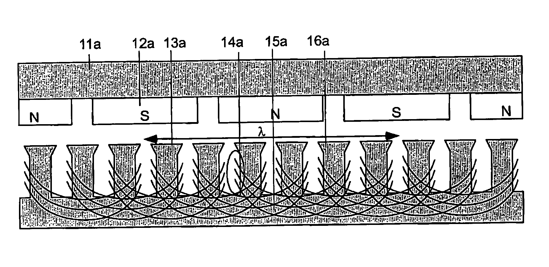
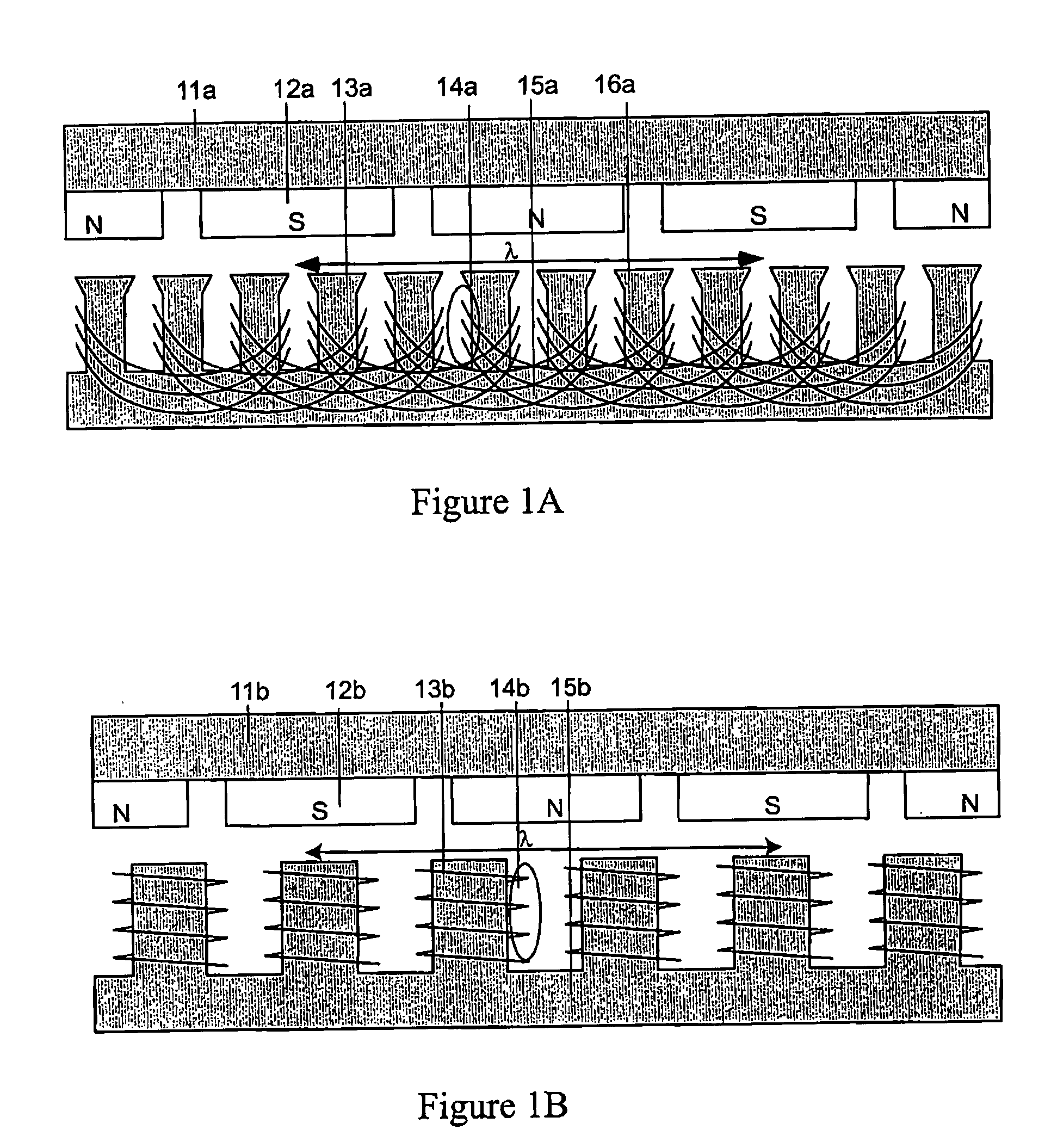
[0043]FIG. 1a is an example of a prior art LSM and FIG. 1b is an example of an LSM according to one practice of the invention. In this Figure the field structures are composed of back iron, 11a and 11b, and permanent magnets, 12a and 12b. The field (or “field structure”) and armature are both 2λ long, where wavelength λ is defined in the Fig. The field has three full-poles and two half-poles with half-poles used at the ends of the field in order to minimize end effects. In an actual motor the field is usually longer th...


PUM


Abstract

Synchronous motors according to the invention operate at higher efficiency, with lower cost, reduced mass and reduced cogging. Magnet dimensions are selected that reduce cogging forces to a negligible amount even though there are fewer slots than normal. Optionally, it is possible to use non-overlapping windings with deeper and open slots. The approach is applicable to both rotary and linear motors and motors using either permanent magnets or electromagnets in the field structure. It is particularly relevant to linear or rotary motors that have a large air gap, and to small motors that must deliver a high ratio of thrust or torque to motor mass.

Description

[0001] This application claims the benefit of priority of U.S. Ser. No. 60 / 326,278, filed Oct. 1, 2001, entitled “Synchronous Machine Design and Manufacturing,” the teachings of which are incorporated herein by reference.BACKGROUND OF THE INVENTION [0002] This patent pertains to the design and manufacture of linear and rotary synchronous motors and generators. The invention has application to virtually all synchronous machines, particularly those that use permanent magnets for the field. [0003] The design and manufacture of synchronous motors has been carried on for over 100 years, but the applications have been primarily for low power motors where synchronism is essential and for high power motors where efficiency and size advantages overcome other disadvantages. [0004] Nicola Tesla invented the induction motor in 1888 and since then the induction motor, also called an asynchronous motor, has dominated the market for rotary motors. The induction motor has been the preferred choice ...

Claims


Application Information

Patent Timeline
Patent Type & Authority Applications(United States)
IPC IPC(8): H02K1/08H02K21/16H02K41/03
CPCH02K1/08H02K41/031H02K29/03H02K21/16H02K2213/03
Inventor THORNTON, RICHARD D.CLARK, TRACY M.
Owner MAGNEMOTION INC
Why Eureka
Try Eureka