Piezoelectric-driven MEMS device and method for manufacturing the same

Inactive Publication Date: 2005-11-03
KK TOSHIBA
View PDF4 Cites 98 Cited by
  • Summary
  • Abstract
  • Description
  • Claims
  • Application Information

AI Technical Summary

Benefits of technology

[0014] The present invention has been made in view of these circumstances. It is an object of the present

Problems solved by technology

The variable capacitor diode, however, has limited applications due to a capacitance change of only on the order of at most 5 times, and a small Q factor of on the order of 20-30 where a higher Q factor indicates less loss.
Under the present situation, the problem of high driving voltage hinders the applications in general consumer products.
Although these methods can create a movable beam and a movable electrode, it is difficult to form a fixed opposing electrode on the underlying substrate.
In the case of a cantilever beam structure, there is a problem that a slight residual stress in the material forming the beam causes the beam to warp upward or downward, and it is thereby significantly difficult to fabricate the structure with a constant distance be

Method used


Image

  • Piezoelectric-driven MEMS device and method for manufacturing the same
  • Piezoelectric-driven MEMS device and method for manufacturing the same
  • Piezoelectric-driven MEMS device and method for manufacturing the same

Examples


first embodiment

(First Embodiment)

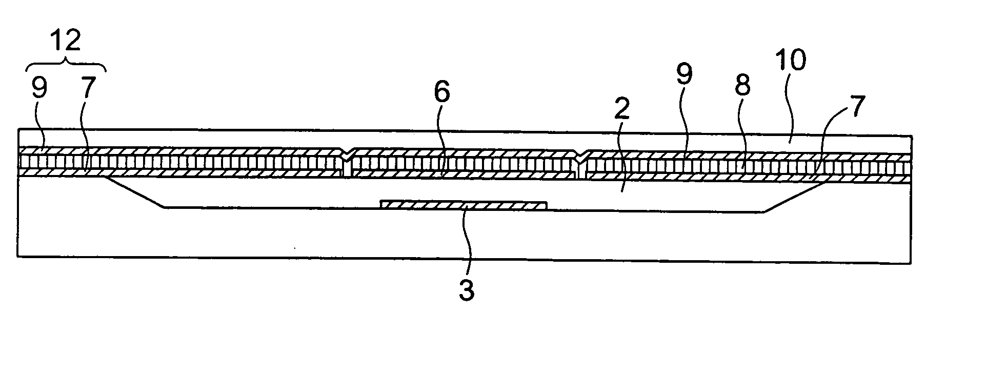
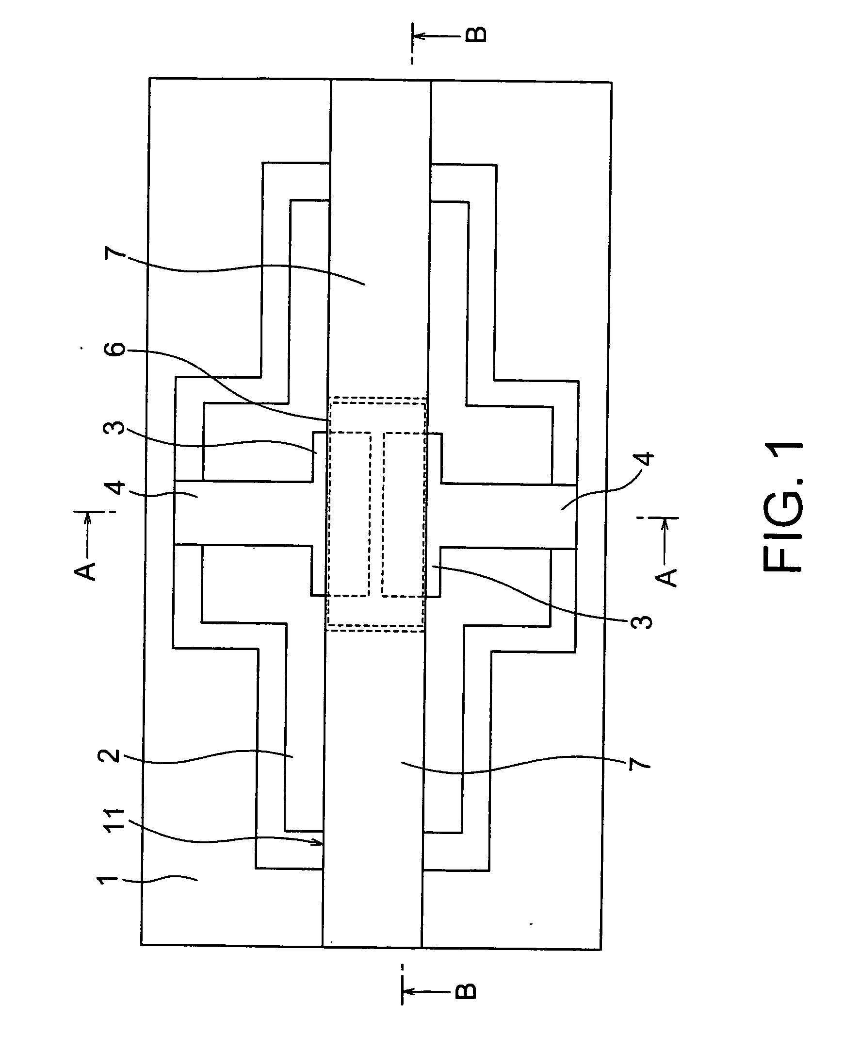
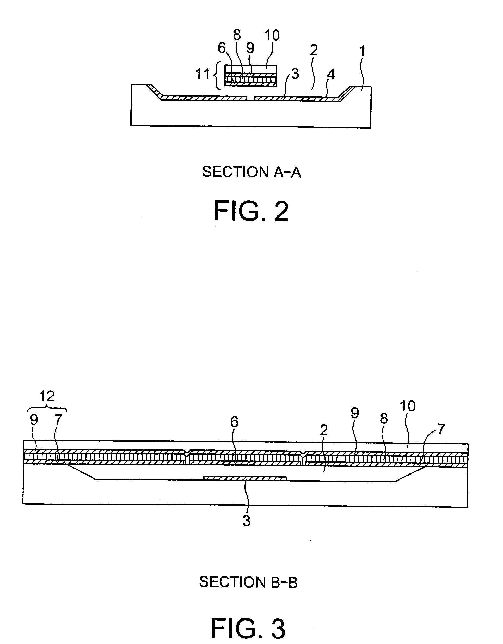
[0048] FIGS. 1 to 3 show a piezoelectric-driven MEMS device according to a first embodiment of the present invention. The piezoelectric-driven MEMS device according to this embodiment is a variable capacitor having a fixed beam structure. In this specification, a “fixed beam” is a beam of which both ends is fixed. FIG. 1 is a plan view of the piezoelectric-driven MEMS device according to the embodiment. FIG. 2 is a cross-sectional view taken along the section line A-A shown in FIG. 1. FIG. 3 is a cross-sectional view taken along the section line B-B shown in FIG. 1.

[0049] The piezoelectric-driven MEMS device according to the embodiment comprises fixed electrodes 3 disposed on a flat bottom of a recessed portion 2 formed in a substrate 1, extension electrodes 4 disposed on the recessed portion 2 and electrically connected to the fixed electrodes 3, and a movable beam 11 having a fixed beam structure disposed above the substrate 1 such that the beam is bridged over ...

second embodiment

(Second Embodiment)

[0065] A piezoelectric-driven MEMS device according to a second embodiment of the present invention will be described with reference to FIGS. 6 to 8. The piezoelectric-driven MEMS device of this embodiment is a variable capacitor comprising a few (two in this embodiment) bimorph structures, in which a piezoelectric film sandwiched between a lower electrode and an upper electrode is laminated to a support layer, juxtaposed in the longitudinal direction of the beam with their polarities alternatively reversed, resulting in a higher curvature. FIG. 6 is a plan view of the piezoelectric-driven MEMS device according to the embodiment. FIG. 7 is a cross-sectional view taken along the section line A-A shown in FIG. 6. FIG. 8 is a cross-sectional view taken along the section line B-B shown in FIG. 6.

[0066] The piezoelectric-driven MEMS device according to the embodiment is configured such that the piezoelectric drive mechanism 12 comprising the lower electrodes 7 and upp...

third embodiment

(Third Embodiment)

[0078] A piezoelectric-driven MEMS device according to a third embodiment of the present invention will be described with reference to FIGS. 17 to 18. FIG. 17 is a plan view of the piezoelectric-driven MEMS device according to the embodiment. FIG. 18 is a cross-sectional view taken along the section line B-B shown in FIG. 17.

[0079] The piezoelectric-driven MEMS device according to the embodiment is configured such that the movable beam 11 having the fixed beam structure in the piezoelectric-driven MEMS device according to the first embodiment is replaced with a movable beam 11 having a cantilever beam structure. The movable beam 11 having a cantilever beam structure comprises two ends, one is supported on the substrate 1 and the other is free. The movable beam 11 comprises a flat piezoelectric film 8 having a narrower width than that of the recessed portion 2 of the substrate, an upper electrode 9 disposed on the piezoelectric film 8, a support film 10 disposed on...


PUM


Abstract

A piezoelectric-driven MEMS device can be fabricated reliably and consistently. The piezoelectric-driven MEMS device includes: a movable flat beam having a piezoelectric film disposed above a substrate with a recessed portion such that the piezoelectric film is bridged over the recessed portion, piezoelectric drive mechanisms disposed at both ends of the piezoelectric film and configured to drive the piezoelectric film, and a first electrode disposed at the center of the substrate-side of the piezoelectric film, and a second electrode disposed on a flat part of the recessed portion of the substrate and facing the first electrode of the movable flat beam.

Description

CROSS-REFERENCE TO RELATED APPLICATION [0001] This application is based upon and claims the benefit of priority from prior Japanese Patent Application No. 2004-133736 filed on Apr. 28, 2004 in Japan, the entire contents of which are incorporated herein by reference. BACKGROUND OF THE INVENTION [0002] 1. Field of the Invention [0003] The present invention relates to a piezoelectric-driven micro-electro-mechanical system (MEMS) device having piezoelectric drive mechanisms using a piezoelectric thin film and a method for manufacturing the same. [0004] 2. Related Art [0005] Conventionally, a variable capacitor diode utilizing a change in thickness of the depletion layer of a PN junction have been used as a variable capacitor. The variable capacitor diode, however, has limited applications due to a capacitance change of only on the order of at most 5 times, and a small Q factor of on the order of 20-30 where a higher Q factor indicates less loss. [0006] On the other hand, a variable capa...

Claims


Application Information

Patent Timeline
IPC IPC(8): H01G5/18B81B3/00H01G7/06H01H57/00H01H59/00H01L41/08H01L41/09H01L41/18H01L41/187H01L41/22H01L41/29H02N1/00H03H9/24
CPCB81B3/0021H01G5/18H01H57/00H01H59/0009H01H2057/006H01G5/16H10N30/2041H10N30/2042
Inventor KAWAKUBO, TAKASHINAGANO, TOSHIHIKOABE, KAZUHIDENISHIGAKI, MICHIHIKO
Owner KK TOSHIBA
Why Eureka
Try Eureka