
T/R module for satellite TT&C ground link

Active Publication Date: 2005-11-03
THE UNITED STATES OF AMERICA AS REPRESETNED BY THE SEC OF THE AIR FORCE
View PDF4 Cites 15 Cited by
  • Summary
  • Abstract
  • Description
  • Claims
  • Application Information

AI Technical Summary

Benefits of technology

[0010] It is therefore an object of the present invention to provide an apparatus that overcomes the dependence of Air Force satellite control network (AFSCN) on mechanically steered parabolic antennas that provide Transmit and Receive (TR) capabilities in support of satellite operations (SATOPS).
[0016] Therefore, it is accurate to say that the present invention (1.) A multi-beam, Transmit and Receive module will greatly increase the number of satellite communication links to the Air Force Satellite Control Network, providing more reliable tracking, telemetry, and command; (2.) The module can accomplish multiple simultaneous operations, with pointing and acquisition taking seconds. As such, the present invention wherein a phase array antenna (PAA) using this Transmit and Receive module can offer superior performance, operability, adaptability, and maintainability for satellite operation.

Problems solved by technology

The current reflector antennas used to support satellite operations are approximately 10 m in diameter and are susceptible to single point failure and long downtime for repair and maintenance.
Because of the mechanical movement and heavy weight of the reflector antenna, operators cannot quickly schedule consecutive satellite contacts.
Because of these factors, the efficiency of reflector antenna operation is low in terms of throughput and turnaround time.
The mechanical nature of the antenna also limits its flexibility to support new SATOPS requirements and operational concepts.
In addition, the high operational and maintenance cost of a large reflector antenna contributes to its high life-cycle cost despite its lower initial cost.
Other limitations include: cable wrap and keyhole effect.
To date, phased array antennas have not been used for satellite TT&C operations primarily because of their high acquisition cost in comparison to technically inferior, but cheaper conventional reflector antennas.
Low cost component design and implementation issues are critical in developing a practical phased array antenna.

Method used


Image

  • T/R module for satellite TT&C ground link
  • T/R module for satellite TT&C ground link
  • T/R module for satellite TT&C ground link

Examples


Embodiment Construction

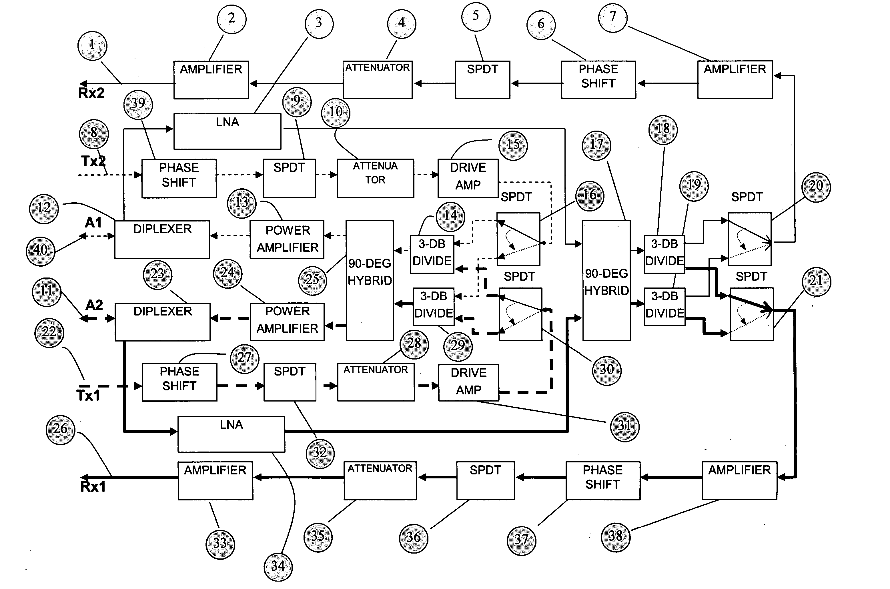
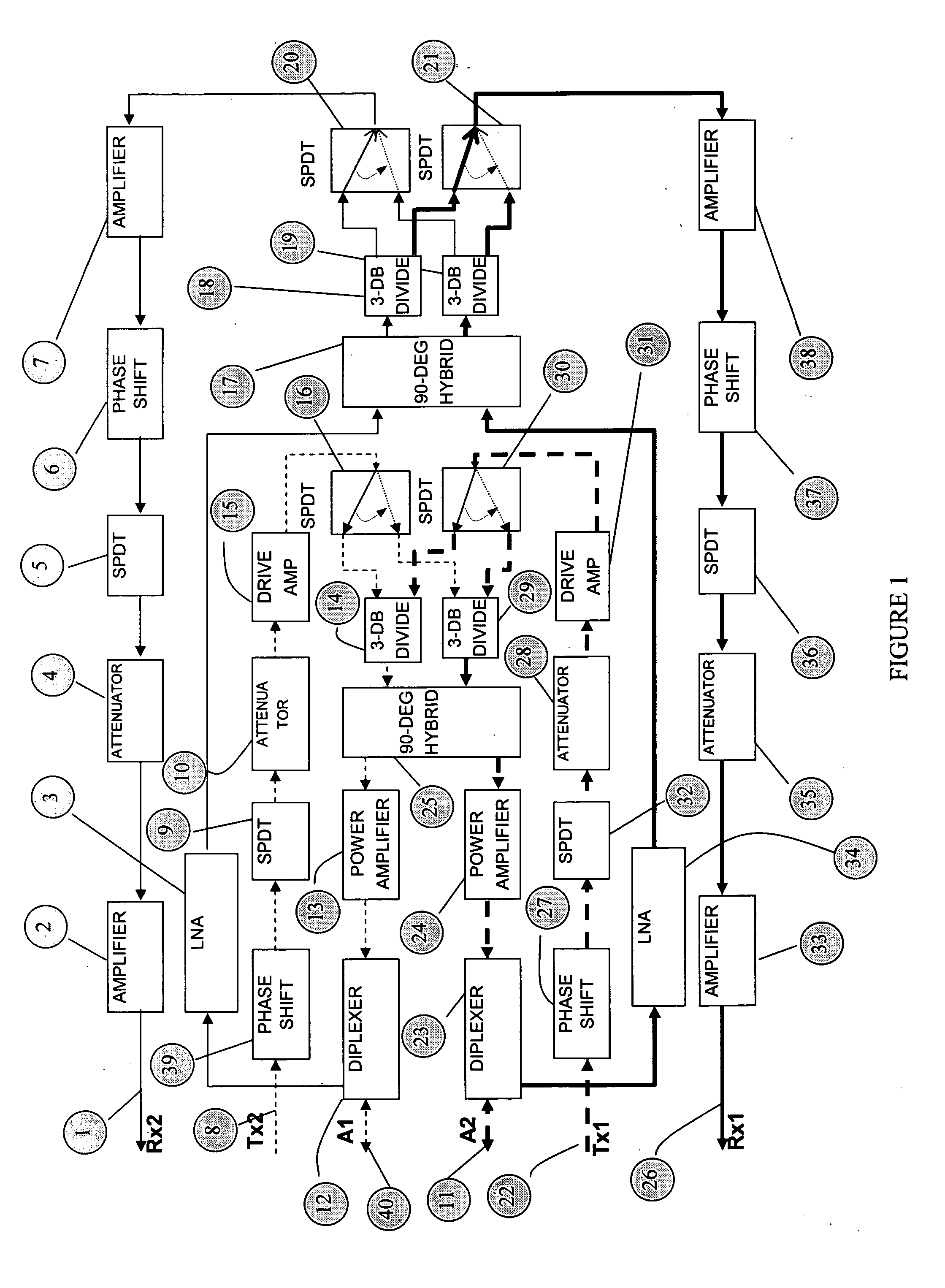
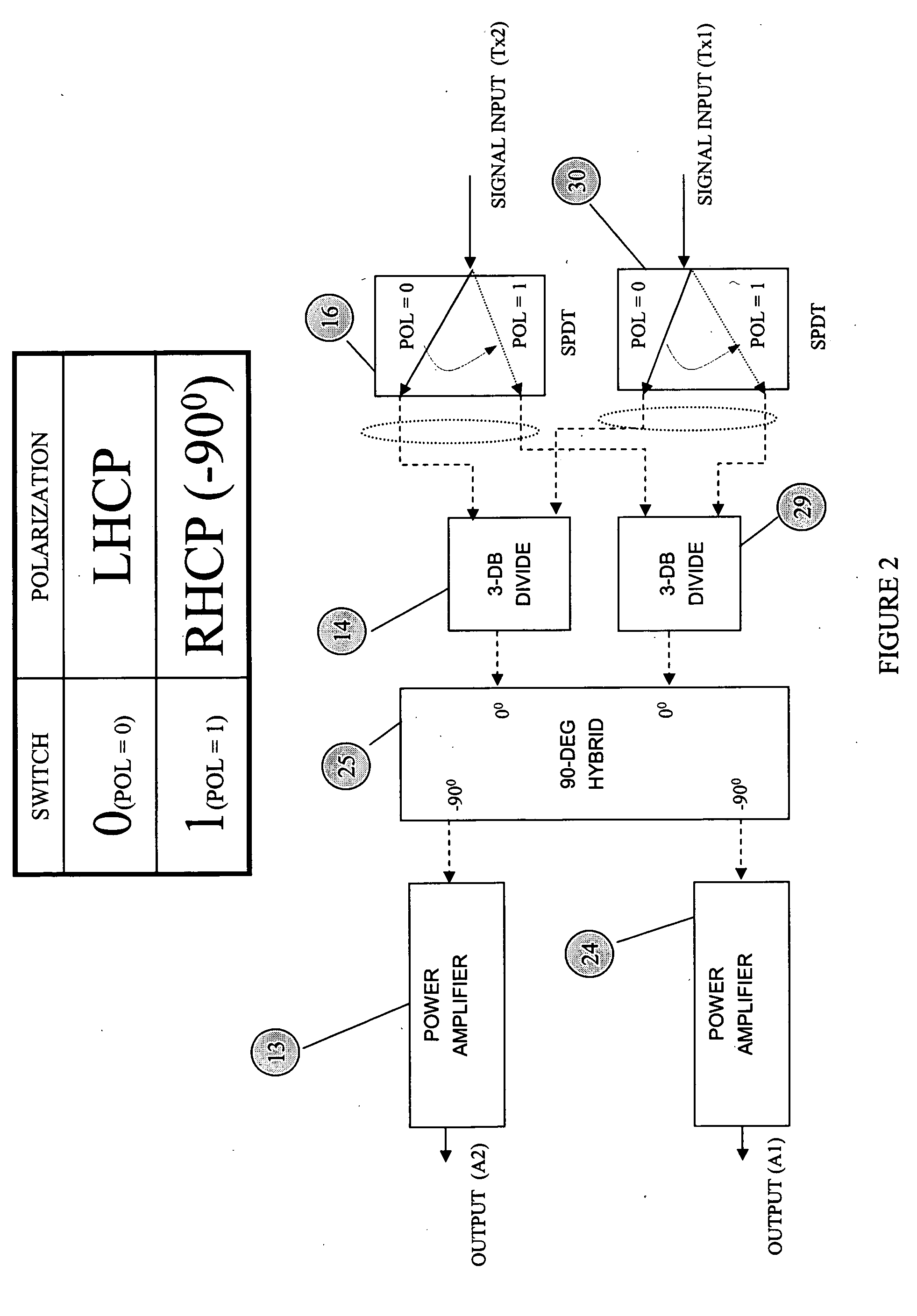
[0027] Referring to FIG. 1, represented are the dual channel transmitter signal inputs 8, 22 and dual receiver signal outputs 1, 26 of the present invention. The transmit frequency of operation is 1.75-2.1 GHz. The receiver frequency of operation is 2.2-2.3 GHz. Each of the dual transmit paths consists of an input 8 or 22 and output to either of the two diplexed antenna ports 11 and 40. The transmitter signal passes through a four-bit phase shifter, 27 or 39 (φ shift of 22.5°, 45°, 90°, 180°), a SPDT switch, 9 or 32 that is used to open / close the RF path, a five-bit attenuator, 10 or 28 (attenuation levels of 1 dB, 2 dB, 4 dB, 8 dB, 16 dB), a pre amplifier, 15 or 31 and then through another absorptive type SPDT switch 16 or 30 before reaching the embedded power combiner 14 or 29. The absorptive SPDT switch is used to induce left hand circular polarization (LHCP) and right hand circular polarization (RHCP) in the signal. A 90-degree hybrid, 25 is used to provide quadrature phase in t...


PUM


Abstract

Transmit / Receive (T / R) module that provides multiple simultaneous ground to satellite links with rapid pointing and acquisition. The (T / R) module incorporates independent gain and phase control. Left-hand or right-hand circular polarization can be supplied to dual feed antennas. Present invention allows each antenna to be independently polarized. Low-cost componentry is utilized throughout. On-board control of the (T / R) module is obtained using a complex programmable logic device (CPLD) and a micro controller. CPLD provides separate control of four phase shifters, attenuators, channel polarization as well as transmitter on / off control. Telemetry is provided through built-in test (BIT) routine.

Description

PRIORITY CLAIM UNDER 35 U.S.C. §119(e) [0001] This patent application claims the priority benefit of the filing date of provisional application Ser. Nos. 60 / 566,788, 60 / 566,768 and 60 / 566,770, all having been filed in the United States Patent and Trademark Office on Apr. 30, 2004 and now incorporated by reference herein.STATEMENT OF GOVERNMENT INTEREST [0002] The invention described herein may be manufactured and used by or for the Government for governmental purposes without the payment of any royalty thereon.BACKGROUND OF THE INVENTION [0003] This invention relates generally to the design of a Transmit and Receive (TR) module, and, more specifically, to such Transmit and Receive modules suitable for a Phase Array Antenna (PAA) which could provide multiple simultaneous ground to satellite links with pointing and acquisition taking seconds. This invention also relates to the field of digital control design where a digital circuit is used to interface with the Antenna Control Compute...

Claims


Application Information

Patent Timeline
IPC IPC(8): H01Q3/22H01Q3/24H01Q3/28H01Q3/38H01Q21/00
CPCH01Q3/28H01Q21/0025H01Q3/38
Inventor TOMASIC, BORISBHARJ, SARJIT S.OLESKI, PAUL J.TURTLE, JOHN P.
Owner THE UNITED STATES OF AMERICA AS REPRESETNED BY THE SEC OF THE AIR FORCE
Learn More