Laminate polarizing plate, a method of producing the same and a liquid crystal display

a technology of polarizing plate and liquid crystal display, which is applied in the direction of polarizing elements, instruments, synthetic resin layered products, etc., can solve the problems of generating birefringence and reducing contrast, and achieve the effect of simplifying the constitution of the plate, simplifying the structure of the plate, and reducing the thickness of the liquid crystal display

Inactive Publication Date: 2005-11-03
SUMITOMO CHEM CO LTD
View PDF10 Cites 31 Cited by
  • Summary
  • Abstract
  • Description
  • Claims
  • Application Information

AI Technical Summary

Benefits of technology

[0023] The laminate polarizing plate of the present invention, although the constitution thereof being simplified, can attain advantages by means of being disposed on one side of a liquid crystal cell, and on the other side of the liquid crystal cell, disposing a phase retarder film having different optical characteristic (a second phase retarder film) together with a second polarizing film; the advantages that being optical characteristics of equal to or more than those exhibited by conventional vertical-alignment mode liquid crystal displays having each one of biaxially phase retarder films independently disposed at upper and lower side. Furthermore, the laminate polarizing plate, due to the constitution thereof being simplified, contributes to make thickness of ...

Problems solved by technology

However, the vertical-alignment mode liquid crystal displays equipping only polarizing plates to a crystal cell, when viewed from inclined directions, remarkably decreases co...

Method used


Image

  • Laminate polarizing plate, a method of producing the same and a liquid crystal display
  • Laminate polarizing plate, a method of producing the same and a liquid crystal display
  • Laminate polarizing plate, a method of producing the same and a liquid crystal display

Examples


example 1

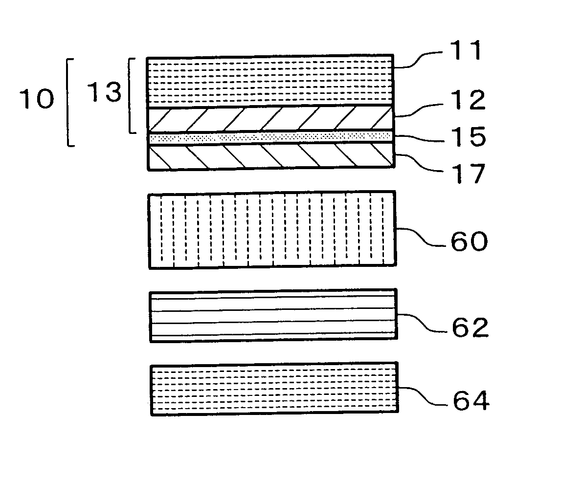
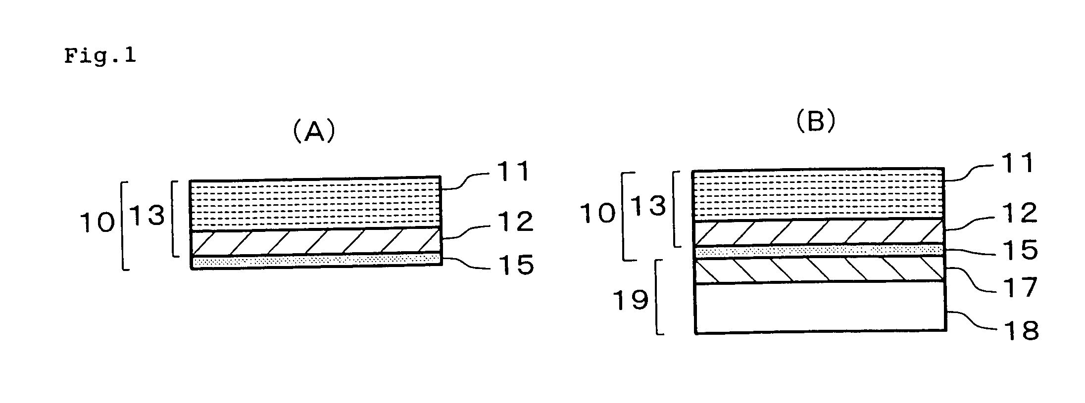
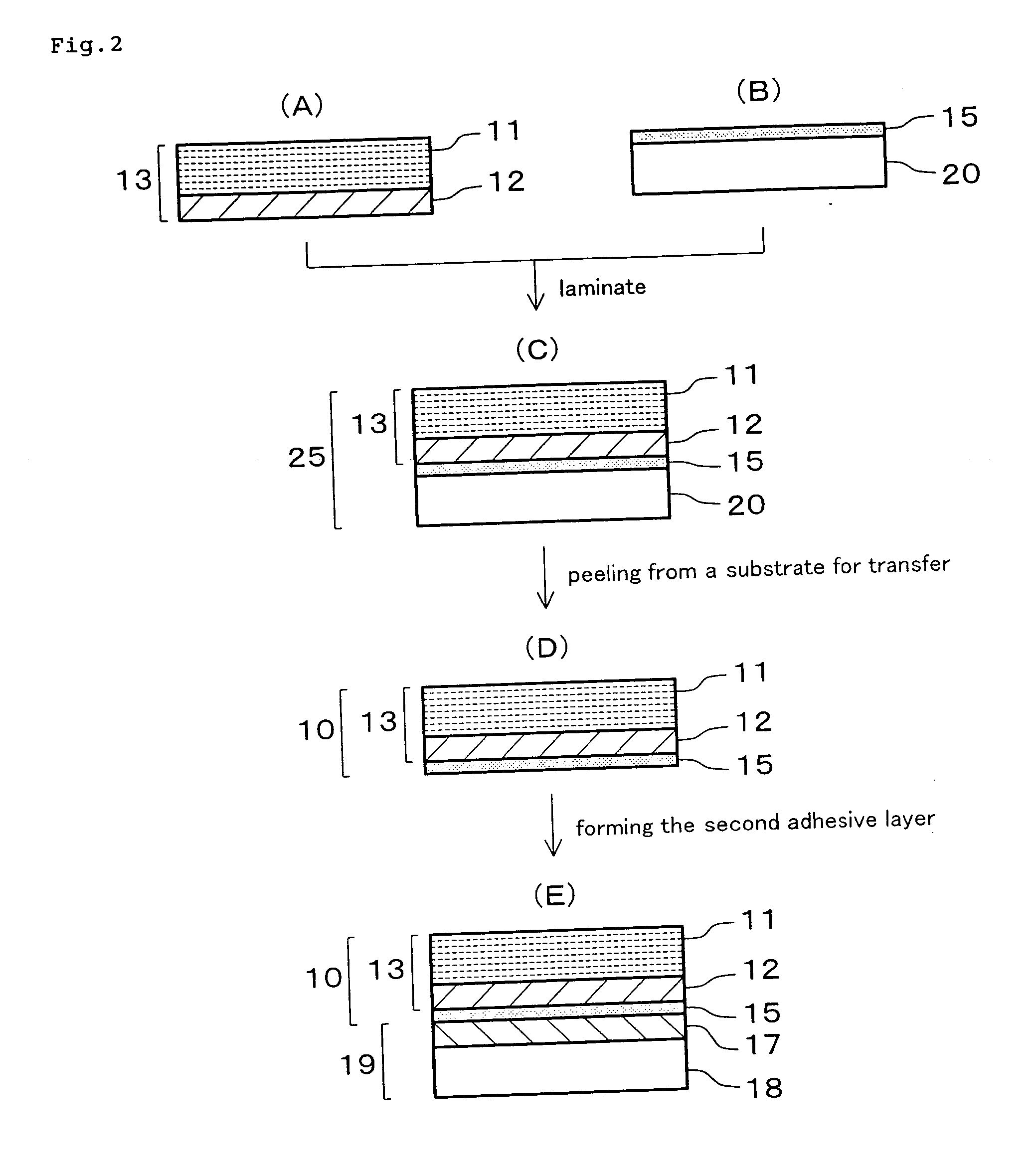
[0114] The coating solution which contained 10.2% of the acrylic resin varnish “Arontack S1601”, 6.75% of the organic modified clay composite “Lucentite STN”, 2.25% of the organic modified clay composite “Lucentite SPN”, 45.6% of toluene and 35.2% of acetone, was prepared. The prepared coating solution was consecutively coated by a die coater on the polyethylene terephthalate film of 38 μm thickness which being subjected to treatment of mould release (the water contact angle at the face subjected to the method of mould release was 110°), followed by passing through a drying oven to be dried, then the coated film was at just passed out from the oven consecutively affixed on the exposed surface thereof with the adhesive side of the polarizing film (trade name of “SUMIKARAN SRW842A”, manufactured by Sumitomo Chemical) which was a polyvinylalcohol-iodine polarizer having protecting layers on both sides thereof and being provided with an adhesive layer at one side thereof; and then the a...

example 2

[0117] The laminate polarizing plate produced in the Example 1 was peeled off from the release film, followed by lamination on the upper face of the VA type liquid crystal cell (a commercial product) by interposing the adhesive layer thereof; and then the lower face of the liquid crystal cell was laminated by interposing an adhesive layer with the second phase retarder film which being composed by an elongated film of a cyclicpolyolefin and having the in-plane retardation value R0=100 nm and the retardation value in the thickness direction R′=130 nm, and then the lower surface of the laminated layer was further laminated by interposing an adhesive layer with the second polarizing film (trade name of “SUMIKARAN SQ0642A”, manufactured by Sumitomo Chemical) which was a polyvinylalcohol-iodine polarizer having a protecting layer on one side thereof, in the manner that the lowest layer of the lower face being the protecting layer of the second polarizing film. In this lamination, the ang...


PUM

PropertyMeasurementUnit
Water contact angleaaaaaaaaaa
Nanoscale particle sizeaaaaaaaaaa

Abstract

The object of the present invention is to provide a laminate polarizing plate of which application to liquid crystal displays is able to simplify constitutions and production procedures of the displays, and to reduce cost thereof; and to provide an industrially advantageous method of producing the compound polarizing plate, and a liquid crystal display using the same. The object is achieved by a laminate polarizing plate comprising a polarizing film, an adhesive layer and a phase retarder film which being laminated in this order, wherein said phase retarder film comprises at least one coating layer having refractive index anisotropy of which an in-plane retardation value (R0) is 0 to 10 nm and a retardation value in the thickness direction (R′) is 40 to 300 nm, wherein said coating layer is formed on a transfer substrate, followed by being transferred on a surface of the adhesive layer of the polarizing film.

Description

BACKGROUND OF THE INVENTION [0001] 1. Field of the Invention [0002] The present invention relates a laminate polarizing plate effective to improve viewing angle characteristics of liquid crystal displays, a method of producing the same and a liquid crystal display comprising the same. [0003] 2. Description of the Related Art [0004] Liquid crystal displays which have characteristics of low power consumption, low drive voltage, light weight and flat panel, rapidly spread to devices displaying information such as cellular phones, handheld terminals, monitors for computer and televisions. On account of development of liquid crystal cell technologies, liquid crystal displays having various modes are proposed and it is getting to solve the problems of liquid crystal display relating response speed, contrast and narrow viewing angle. The liquid crystal displays, however, are still pointed out on the problem of their narrower viewing angle compared with cathode ray tubes (CRT); hence, vario...

Claims


Application Information

Patent Timeline
IPC IPC(8): G02B5/30G02F1/1335G02F1/13363
CPCG02B5/3083G02F1/133634G02F1/133528G02B5/305C08J5/18B32B27/08G02B1/04C08L2203/16
Inventor MATSUOKA, YOSHIKI
Owner SUMITOMO CHEM CO LTD
Why Eureka
Try Eureka