Electrochromic element

a technology of ec elements and ec elements, applied in non-linear optics, instruments, optics, etc., can solve the problems of difficult control of white balance, inability to use conventional ec elements instead of nd filters, etc., to suppress characteristic deterioration, suppress characteristic deterioration, inhibit transparency

Inactive Publication Date: 2005-11-10
MURAKAMI CORP
View PDF3 Cites 35 Cited by
  • Summary
  • Abstract
  • Description
  • Claims
  • Application Information

AI Technical Summary

Benefits of technology

[0041] In the present invention, the solid electrolyte may comprise, for example, Ta2O5 as a main component. As the materials making up the intermediate layer, materials which are transparent (even in the case of metals, transparency can be obtained, if it is thin enough), and which have electric conductivity or characteristics of the solid electrolyte, can be used. Specifically, examples of the metals making up the intermediate layer include Ag, Au, Cr, Al, and Pd or a composite (a laminate of the metal oxide other than the nickel oxide and the metal, a mixture or such) of two or more thereof as a main component. Also, the metal oxide making up the intermediate layer may comprise any one of SnO2, ZnO, In2O3, ITO, Al2O3, SiO2, TiO2, Sb2O5, and ZrO2, or a composite of two or more thereof as a main component. Also, the oxidative coloration layer may comprise a nickel oxide as a main component. Further, the nickel oxide contained in the oxidative coloration layer may comprise NiO as a main component. Although, the thickness of the intermediate layer cannot be generalized because it depends upon the material, the lower limit is a thickness which can obtain an effect of suppressing characteristic deterioration due to repeated cycles of coloration and discoloration, while the upper limit is a thickness, which does not inhibit a transparency required for an intended application. In the case where the intermediate layer is an insulating material, the response change for the worse if the film becomes thicker, the upper limit of the thickness is a thickness which is sufficient for response required depending upon an intended application. For example, in the case of SnO2, the thickness is desirably not more than 5 nm and less than 70 nm. If the thickness is less than 5 nm, the effect of suppressing characteristic deterioration due to repeated cycles of coloration and discoloration cannot be obtained in a sufficient manner. Conversely, if it exceeds 70 nm, the response gradually becomes slower at the time of discoloration.

Problems solved by technology

However, since the conventional EC element colors blue, which leads to bluish image being taken, and which makes it difficult to control white balance, the conventional EC element cannot be used instead of the ND filter.

Method used


Image

  • Electrochromic element
  • Electrochromic element
  • Electrochromic element

Examples


first embodiment

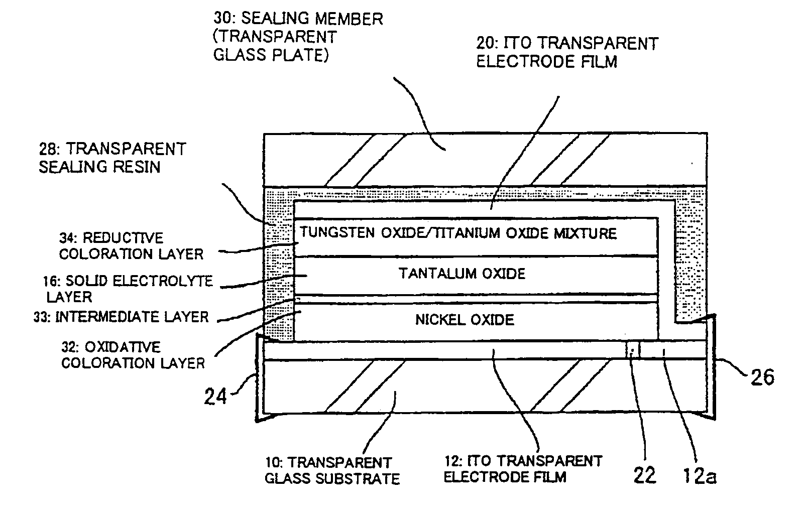
[0065] First embodiment of an EC element according to the present invention is shown in FIG. 1. This EC element is composed of the EC element of FIG. 3 described above having a gray color at the time of coloration having a device for measuring durability according to the present invention. The same portions as those of FIG. 3 are assigned to the same symbols. The matters which are not described hereinbellow are the matters which have already been described in the description of FIG. 3 and, thus, as for these matters, see the description of FIG. 3. In FIG. 1, an ITO transparent electrode film 12 making up a lower electrode film is formed on a transparent glass substrate 10, a nickel oxide film 32 making up an oxidative coloration layer, an intermediate layer 33, a tantalum oxide film 16 making up a solid electrolyte layer, a mixed film 34 comprising a tungsten oxide and a titanium oxide making up a reductive coloration layer, an ITO transparent electrode film 20 making up an upper el...

second embodiment

[0092]FIG. 16 is a drawing showing a second embodiment of the present invention. This embodiment is an EC element in the embodiment shown in FIG. 1 where the arrangement of the nickel oxide film 32 making up the oxidative coloration layer and the mixed film 34 comprising a tungsten oxide and a titanium oxide making up the reductive coloration layer are altered. Parts common to those of the embodiment of FIG. 1 are assigned to the same symbols.

third embodiment

[0093]FIG. 17 is a drawing showing a third embodiment of the present invention. In this embodiment, an anti-glare mirror for an automobile or such is configured whose surface side is at the substrate side. Parts common to those of the embodiment of FIG. 1 are assigned to the same symbols. An ITO transparent electrode film 12 making up a lower electrode film is formed on a transparent glass substrate 10, a nickel oxide film 32 making up an oxidative coloration layer, an intermediate layer 33, a tantalum oxide film 16 making up a solid electrolyte layer, a mixed film 34 comprising tungsten oxide and titanium oxide making up a reductive coloration layer, a reflecting electrode film 44 made of Al, Ni, Cr, or such making up an upper electrode film are formed on this order. A parting line 22 is previously formed on one edge of the lower ITO transparent electrode film 12 by a laser etching process, so that an area 12a of the edge portion is electrically partitioned. One edge of the upper r...


PUM

PropertyMeasurementUnit
thicknessaaaaaaaaaa
thicknessaaaaaaaaaa
thicknessaaaaaaaaaa

Abstract

Deterioration of characteristics due to repeated cycles of coloration and discoloration in an electrochromic element comprising an oxidative coloration layer composed of a nickel oxide and a electrolyte composed of a solid electrolyte is suppressed. A lower ITO transparent electrode film 12 is formed on a transparent substrate 10. A nickel oxide film 32 making up an oxidative coloration layer, an intermediate layer 33, a tantalum oxide film making up a solid electrolyte layer, a mixed film comprising a tungsten oxide and a titanium oxide making up a reductive coloration layer, and an upper ITO transparent electrode film 20 making up an upper electrode film are formed on the lower ITO transparent electrode film 12 on this order. The intermediate layer 33 is a transparent film comprising a metal oxide such as SnO2, a metal such as Al, or a composite of the metal oxide and the metal.

Description

BACKGROUND ARTS [0001] 1. Field of the Invention [0002] The present invention relates to an electrochromic (herein after simply referred to as “EC”) element, comprising an oxidative coloration layer composed of an nickel oxide and an electrolyte layer composed of a solid electrolyte. More, specifically, the invention relates to an EC element whose deterioration of characteristics due to repeated cycles of coloration and discoloration can be suppressed. [0003] 2. Description of Related Arts [0004] An EC element is an element which utilizes an EC phenomenon to reversibly carry out coloration and discoloration, and the EC element has been used in an anti-glare mirror, a dimming glass, a display elements and the like. FIG. 2 shows an example of a laminated cross-section of a conventional EC element. In this element, the whole of the element is made transparent. On a transparent glass substrate 10, an ITO (Indium Tin Oxide) transparent electrode film 12 making up a lower electrode film, ...

Claims


Application Information

Patent Timeline
Patent Type & Authority Applications(United States)
IPC IPC(8): G02F1/1524G02F1/153
CPCG02F1/1523G02F2001/1502G02F1/1533G02F1/1524
Inventor FUKAZAWA, AKIHIKOMINAMI, CHIHIRO
Owner MURAKAMI CORP
Why Eureka
Try Eureka