Complex objective lens, optical head, optical information apparatus, computer, optical disk player, car navigation system, optical disk recorder, and optical disk server
- Summary
- Abstract
- Description
- Claims
- Application Information
AI Technical Summary
Benefits of technology
Problems solved by technology
Method used
Image
Examples
embodiment 1
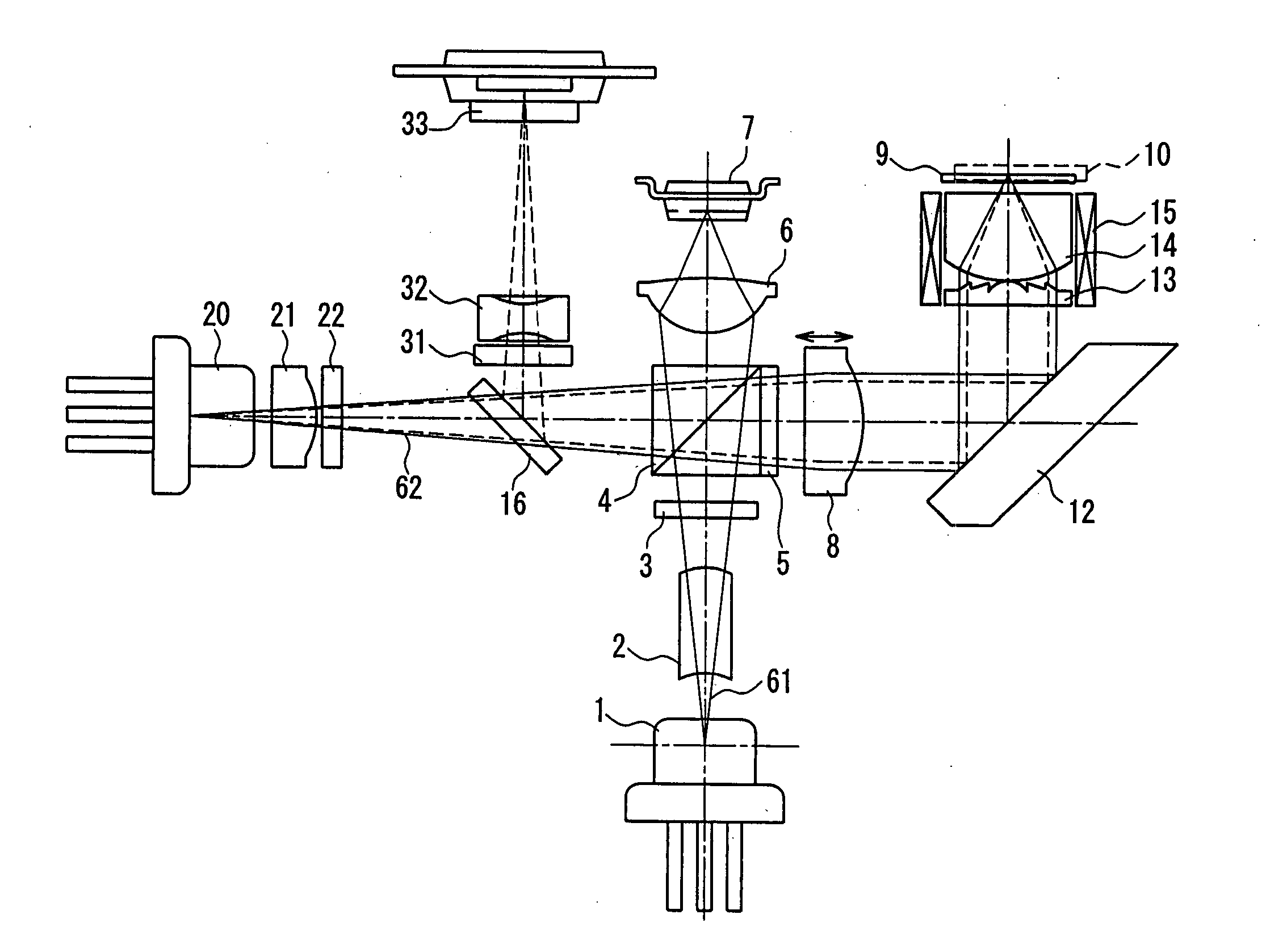
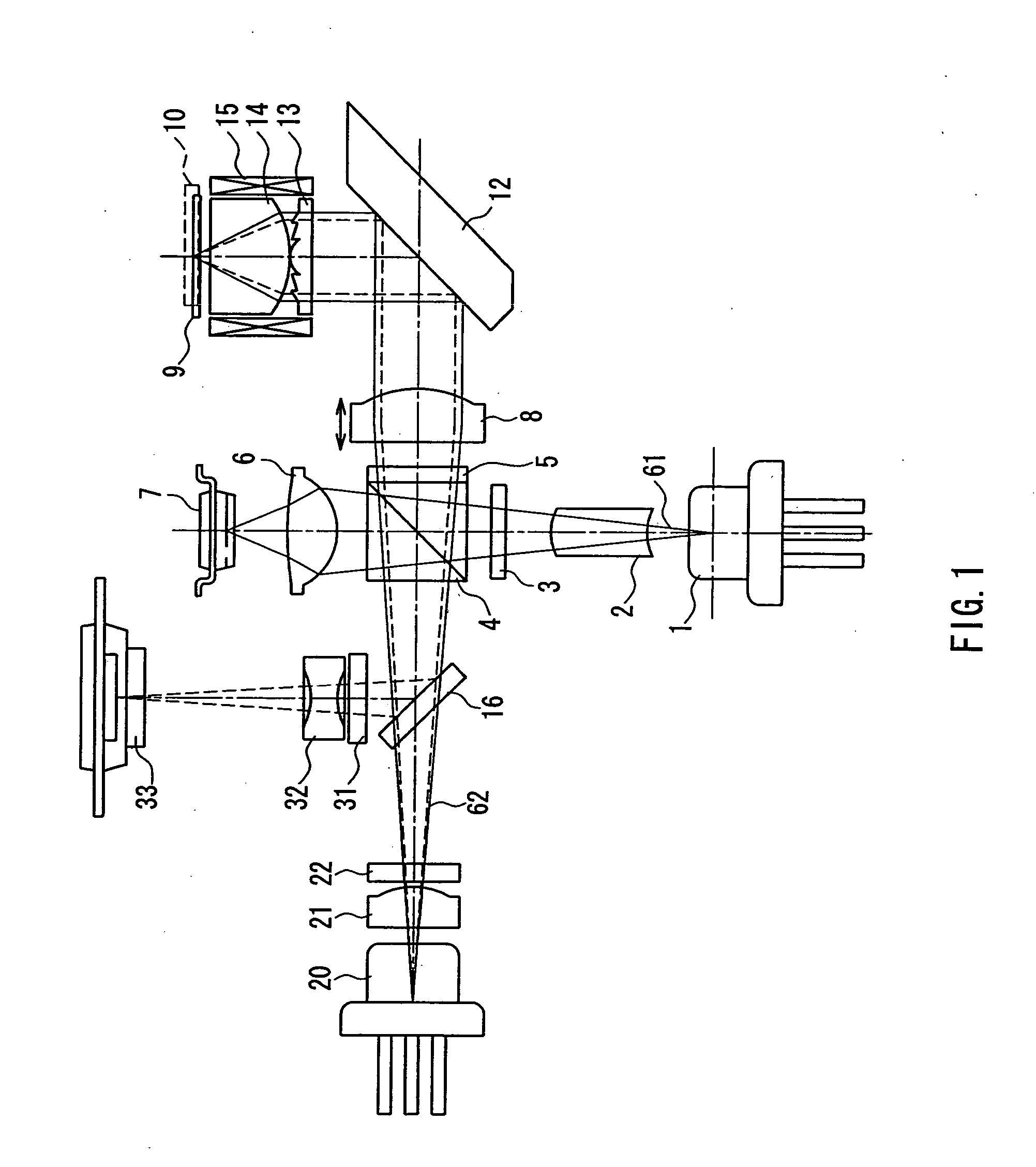
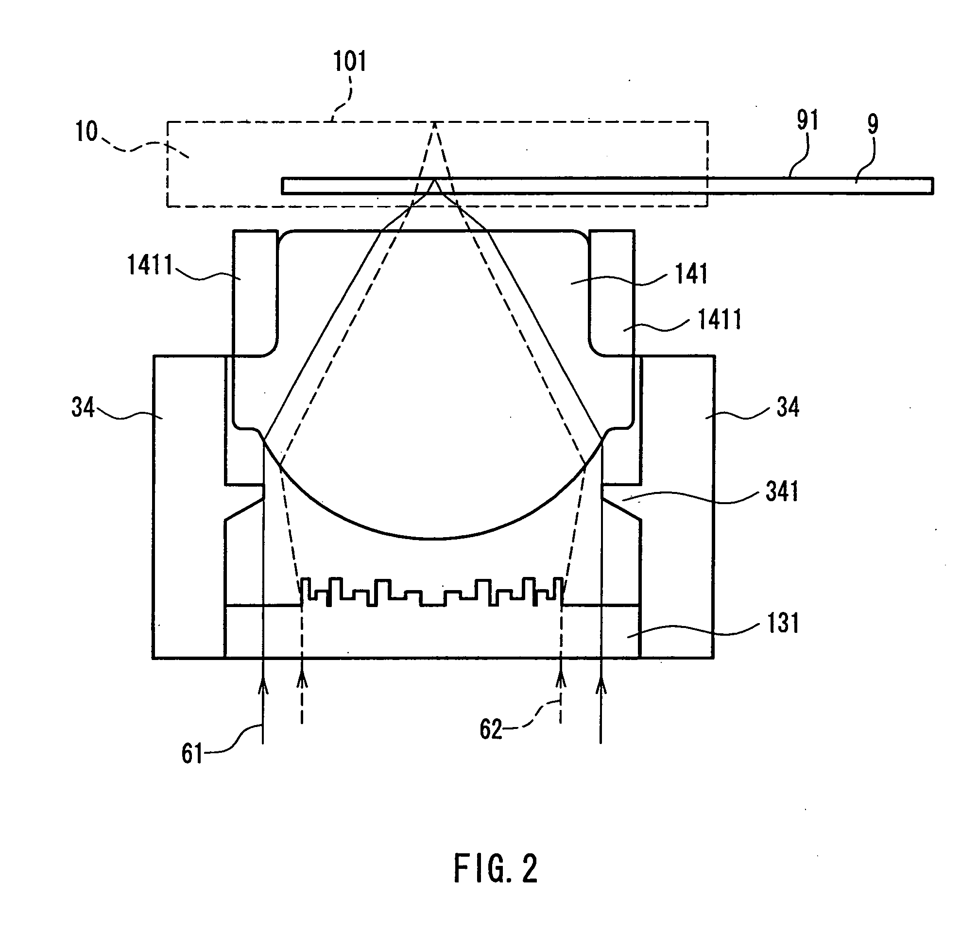
[0111]FIG. 1 is a cross-sectional view showing one exemplary configuration of an optical head according to Embodiment 1 of the present invention. In FIG. 1, reference numeral 1 denotes a blue laser light source as a first laser light source for emitting a first light beam having a wavelength λ1 (390 nm to 415 nm: in general, 405 nm is used often, so that a wavelength of 390 nm to 415 nm will be collectively referred to as “about 405 nm”); 20 denotes a red laser light source as a second laser light source for emitting a second light beam having a wavelength λ2 (630 nm to 680 nm: in general, 660 nm is used often, so that a wavelength of 630 nm to 680 nm will be collectively referred to as “about 660 nm”); 8 denotes a collimator lens; 12 denotes a rising mirror that bends an optical axis; 13 denotes a hologram (diffraction type optical element); and 14 denotes an objective lens as a refraction type lens. Herein, the hologram 13 and the objective lens 14 constitute a complex objective l...
embodiment 2
[0146] Next, Embodiment 2 of the present invention will be described. The overall configuration of an optical head according to the present embodiment is the same as that shown in FIG. 1 referred to in the description of Embodiment 1. In the present embodiment, the configuration of the hologram 13 and the objective lens 14 shown in FIG. 1 is different from that of Embodiment 1.
[0147]FIG. 5 is a cross-sectional view showing a specific example of a complex objective lens composed of the hologram 13 and the objective lens 14 shown in FIG. 1. In FIG. 5, reference numeral 132 denotes a hologram. The hologram 132 diffracts the blue light beam 61 with a wavelength λ1 to effect a convex lens action, and diffracts the red light beam 62 with a wavelength λ2 to effect a concave lens action, as described later. Herein, the diffraction of the lowest order that effects a convex lens action is defined as +1st-order diffraction. Then, the red light beam 62 is subjected to a concave lens action by ...
embodiment 3
[0163] Next, Embodiment 3 of the present invention will be described. The overall configuration of an optical head according to the present embodiment is the same as that shown in FIG. 1 referred to in the description of Embodiment 1. In the present embodiment, the configuration of the hologram 13 shown in FIG. 1 is different from those of Embodiments 1 and 2.
[0164]FIGS. 8A and 8B are a plan view and a cross-sectional view showing a specific example of the hologram 13 shown in FIG. 1, respectively. In FIGS. 8A and 8B, reference numeral 133 denotes a hologram. An inner circumferential portion 133C of the hologram 133 is the same as the inner circumferential portion 132C of the hologram 132 illustrated and described in Embodiment 2. Furthermore, a grating pitch of an outer peripheral portion 133B also is the same as that of the outer peripheral portion 132B of the hologram 132 illustrated and described in Embodiment 2. However, as shown in FIG. 8B, the cross-sectional shape of a grat...
PUM
 Abstract
Description
Claims
Application Information
 - R&D
- Intellectual Property
- Life Sciences
- Materials
- Tech Scout
- Unparalleled Data Quality
- Higher Quality Content
- 60% Fewer Hallucinations
Browse by: Latest US Patents, China's latest patents, Technical Efficacy Thesaurus, Application Domain, Technology Topic, Popular Technical Reports.
© 2025 PatSnap. All rights reserved.Legal|Privacy policy|Modern Slavery Act Transparency Statement|Sitemap|About US| Contact US: help@patsnap.com


