This helps you quickly interpret patents by identifying the three key elements:
Problems solved by technology
Method used
Benefits of technology
Benefits of technology
[0019] By doing this, it is possible to realize a dispersion-compensated optical fiber in which, even if it is wound in a small reel, a module loss is low, there is not an increase of a loss which is caused by a bending loss, there is not an outstanding increase of a loss which is caused by a bending loss in a long wavelength. Thus, it is possible to contain the dispersion-compensated optical fiber in a smaller module with reference to a conventional module of the dispersion-compensated optical fiber. Even if a module for a dispersion-compensated optical fiber by winding it in a small coil, it is possible to realize a module for the dispersion-compensated optical fiber which has a stable temperature characteristics such that a fluctuation of the module loss is ±0.5 dB or lower in an ordinary usage temperature range (−5° C. to +70° C.).
[0038] By doing this, it is possible to realize a dispersion-compensated optical fiber in which, even if it is wound in a small reel, a module loss is low, there is not an outstanding increase of a loss which is caused by a bending loss in a long wavelength. Thus, it is possible to contain the dispersion-compensated optical fiber in a smaller module with reference to a conventional module of the dispersion-compensated optical fiber. Compatibly, the RDS is 0.0026 nm−1 to 0.035 nm−1 in 1.57 μm to 1.63 μm; thus, is it possible to realize a dispersion-compensated optical fiber which is suitable for the S-SMF which has typically an RDS such as 0.0029 nm−1 in 1.59 μm.
Problems solved by technology
Next problem is an accumulated wavelength dispersion.
Therefore, if a signal is transmitted by using this optical fiber, the transmission characteristics deteriorates greatly by an influence of the accumulated wavelength dispersion in a long distance transmission.
However, the technology which are disclosed in the above mentioned publication and a report by an institute was not sufficient for realizing a small module while restricting an increase of a loss which is caused by a bending loss over an entire range of the usage wavelength.
Method used
Image
Click on the blue label to locate the original text in one second.
Reading with bidirectional positioning of images and text.
Examples
example 1
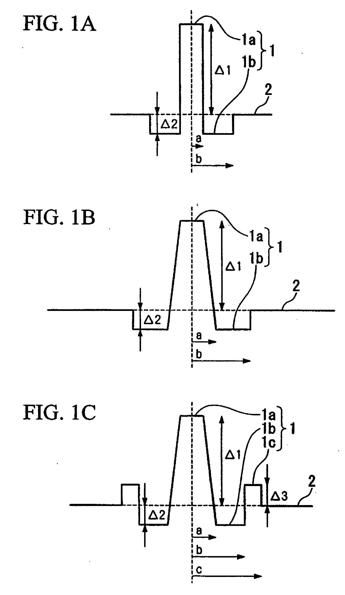
[0079] Dispersion-compensated optical fibers are produced with a W-type profile shown in FIG. 1(b) and a W-type profile with a ring shown in FIG. 1(c) according to a commonly known method such as a VAD method, an MCVD method, or a PCVD method. Under such a condition, values such as Δ1, Δ2, Δ3, b / a, c / b, a core radius, a diameter of the cladding, an outer diameter of a first coating layer, and an outer diameter of a second coating layer are made so as to be values shown in a TABLE 1 under condition that an atmospheric oxygen density should be 0.1% or lower (0.0% when it is displayed) when an ultraviolet-ray-curable resin is hardened while being drawn.
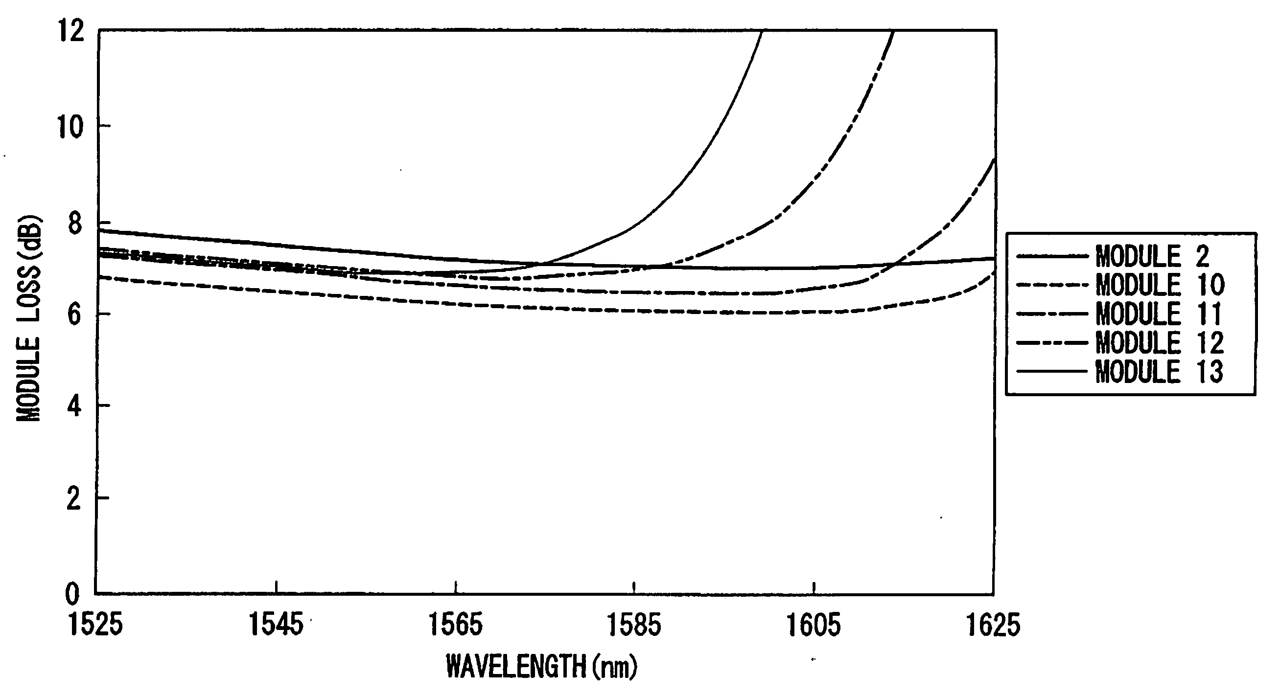
[0080] Here, a dispersion-compensated optical fiber in No. 1 is produced so as to have an outer diameter of the conventional cladding and a coating structure for a purpose of a comparison. The dispersion-compensated optical fibers shown in No. 2 to No. 6 are examples of the optical fiber according to the present invention.
TABLE 1FIRST...
example 2
[0086] Four variations of dispersion-compensated optical fibers with a W-type profile shown in FIG. 1(c) are produced according to a commonly known method such as a VAD method, an MCVD method, or a PCVD method. Under such a condition, values such as Ä1, Ä2, Ä3, b / a, c / b, and a core radius are made so as to be values shown in a TABLE 4 under condition that an atmospheric oxygen density should be 0.1% or lower (0.0% when it is displayed) when an ultraviolet-ray-curable resin is hardened while being drawn.
[0087] Here, a dispersion-compensated optical fibers in No. 7 to No. 9 are produced so as to have conventional dispersion characteristics for a purpose of a comparison. The dispersion-compensated optical fiber shown in No. 2 is an example of the optical fiber according to the present invention.
TABLE 4FIRSTSECONDCLADDINGCOATINGCOATINGCOREOUTEROUTEROUTERSURFACERADIUSDIAMETERDIAMETERCIAMETERVISCOSITYNo.Δ1(%)Δ2(%)Δ3(%)b / ac / b(μm)(μm)(μm)(μm)(gf / mm)22.00−0.460.362.71.56.4901351750.171.60...
example 3
[0093] Five variations of dispersion-compensated optical fibers with a W-type profile shown in FIG. 1(b) or with a W-type profile with ring as shown in FIG. 1(c) are produced according to a commonly known method such as a VAD method, an MCVD method, or a PCVD method Under such a condition, values such as Ä1, Ä2, Ä3, b / a, c / b, a core radius, a diameter of the cladding, an outer diameter of a first coating layer, and an outer diameter of a second coating layer are made so as to be values shown in a TABLE 1 under condition that an atmospheric oxygen density should be 0.1% or lower (0.0% when it is displayed) when an ultraviolet-ray-curable resin is hardened while being drawn.
[0094] Here, a dispersion-compensated optical fibers in No. 12 to No. 13 are produced so as to have conventional dispersion characteristics for a purpose of a comparison. The dispersion-compensated optical fiber shown in No. 2, No. 10, and No. 11 are examples of the optical fiber according to the present invention...
PUM
Abstract
A dispersion-compensated optical fiber which does not cause an increase in a loss if it is wound in a small reel and has a stable temperature characteristics is provided. A dispersion-compensated optical fiber is formed such that, in at least a wavelength between 1.53 to 1.63 μm, a bending loss of 20 mm bending diameter is 5 dB / m or lower, a wavelength dispersion is −120 ps / nm / km or lower, a cut-off wavelength under a usage condition is 1.53 μm or lower, an outer diameter of the cladding is 80 to 100 μm, an outer diameter of a coating is 160 to 200 μm, a viscosity of a surface of a coating resin is 10 gf / mm or lower. It is set such that b / a is 1.5 to 3.5, c / b is 1.2 to 2.0, a radius of a core is 4 to 8 μm, Δ1 is +1.6% to +2.6%, Δ2 is −0.30% to −1.4%, and Δ3 is −0.3 0% to +1.0%. Young's modulus of a first coating layer is 0.15 kgf / nun 2 or lower and its thickness is 20 to 30 μm. Young's modulus of a second coating layer is 50 kgf / mm2 or lower and its thickness is 15 to 30 μm.
Description
TECHNICAL FIELD [0001] The present invention relates to a dispersion-compensated optical fiber which compensates a wavelength dispersion for a 1.3 μm bandwidth zero-dispersion single mode optical fiber (Standard Single Mode Fiber, hereinafter called an “S-SMF” for short) which has a zero-dispersion wavelength in 1.3 μm bandwidth or a non-zero dispersion shift optical fiber (Non-Zero Dispersion Shifted Fiber, hereinafter called as “NZ-DSF” for short. In particular, the present invention relates to a dispersion-compensated optical fiber in which there are few deterioration in characteristics even if it is formed to be a module by winding in a small reel. [0002] The present application is based on patent applications No. 2003-057013 and No. 2002-069077 filed in Japan, the content of which are incorporated herein by reference. BACKGROUND ART [0003] In general, if a transmission distance for an optical fiber transmission path is formed to be long, a transmission speed is made to be high,...
Claims
Application Information
Patent Timeline
Application Date:The date an application was filed.
Publication Date:The date a patent or application was officially published.
First Publication Date:The earliest publication date of a patent with the same application number.
Issue Date:Publication date of the patent grant document.
PCT Entry Date:The Entry date of PCT National Phase.
Estimated Expiry Date:The statutory expiry date of a patent right according to the Patent Law, and it is the longest term of protection that the patent right can achieve without the termination of the patent right due to other reasons(Term extension factor has been taken into account ).
Invalid Date:Actual expiry date is based on effective date or publication date of legal transaction data of invalid patent.

