Spraying method and apparatus
- Summary
- Abstract
- Description
- Claims
- Application Information
AI Technical Summary
Benefits of technology
Problems solved by technology
Method used
Image
Examples
Embodiment Construction
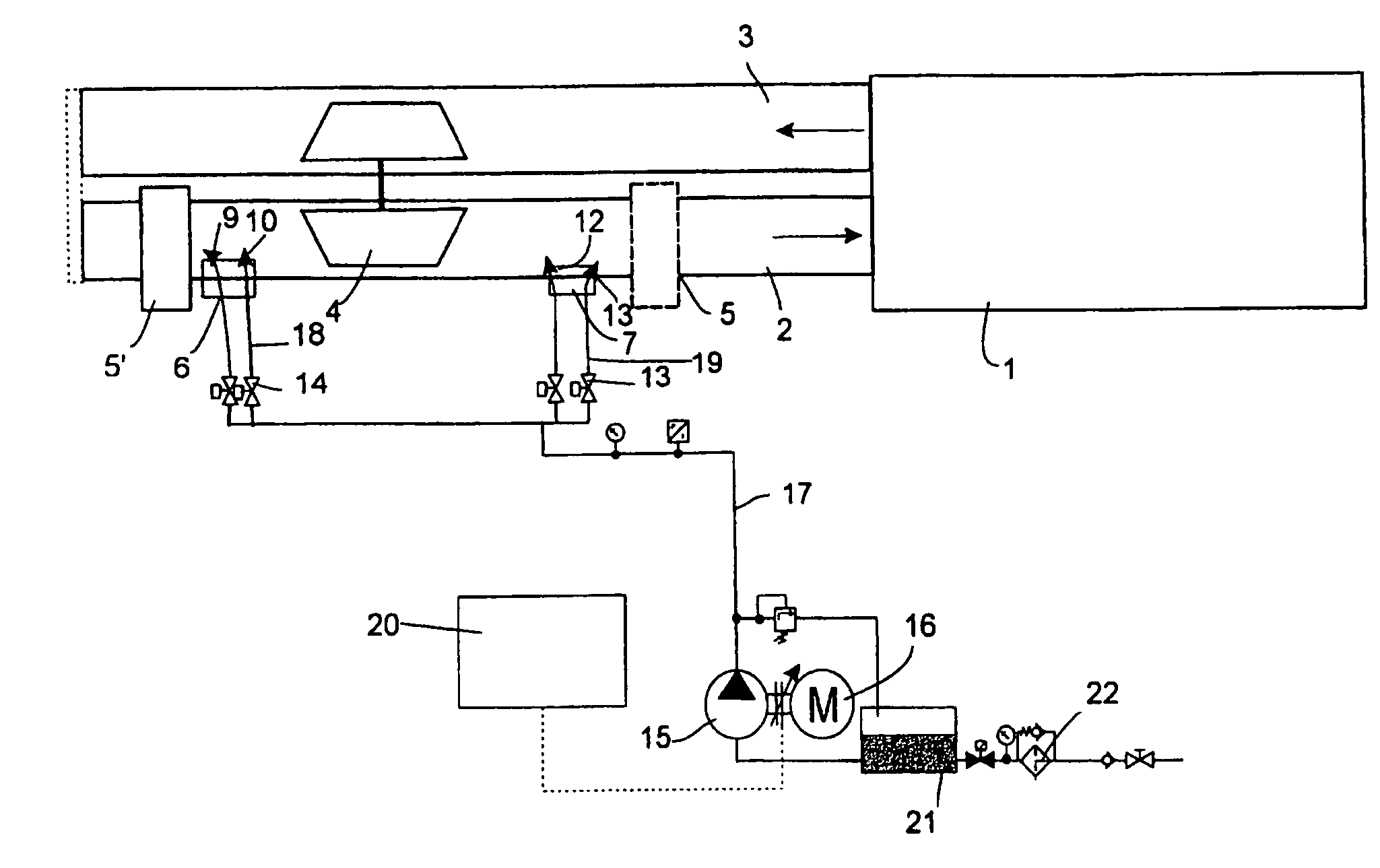
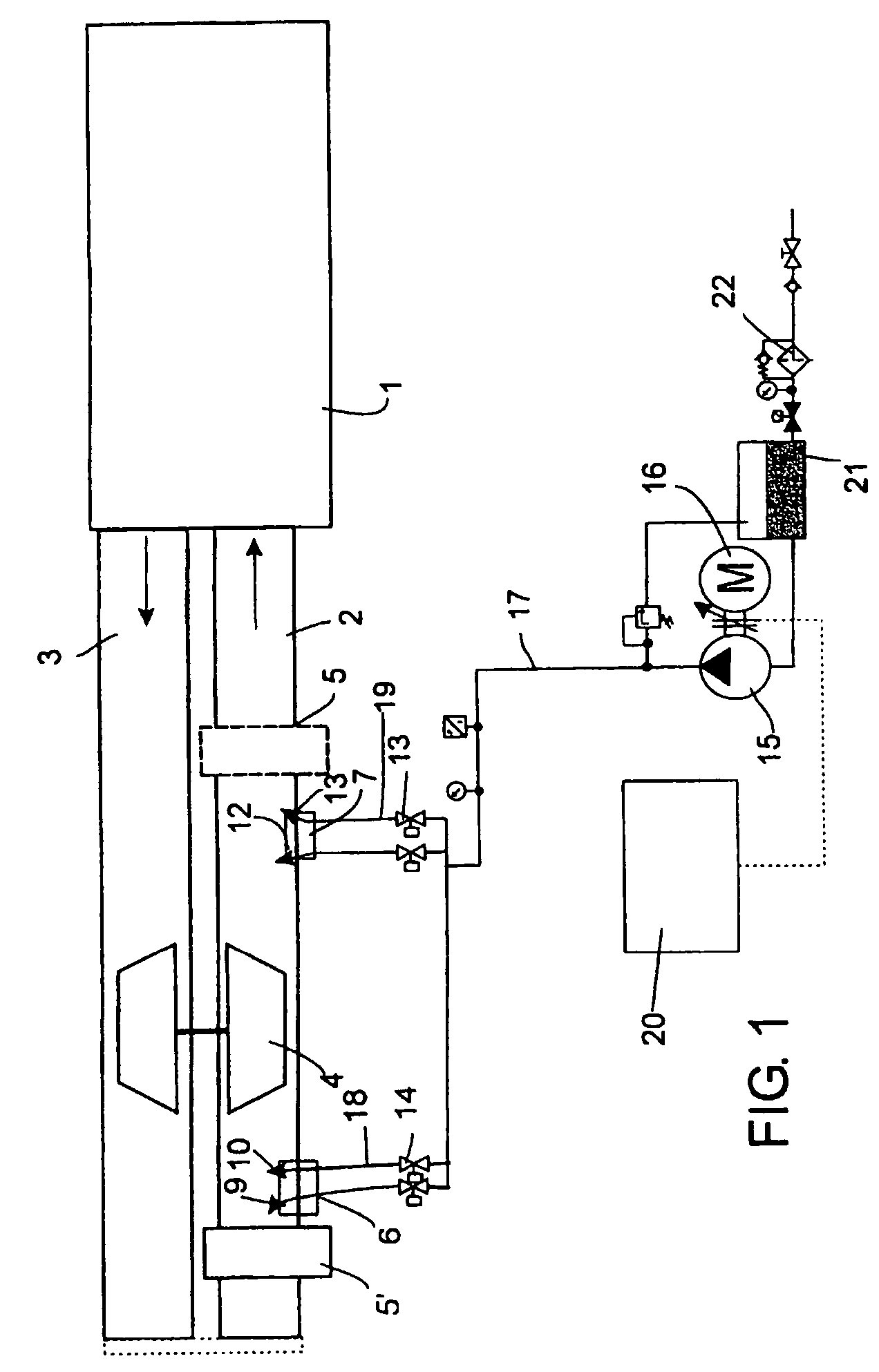
[0016]FIG. 1 is a diagrammatic representation of a apparatus according to the invention, installed in connection with the air intake duct 2 of a piston engine, such as a diesel engine. The air intake duct 2 and the exhaust gas duct 3 are shown in a simplified form in the FIGURE. The engine presented in the FIGURE is provided with a turbocharger 4, which feeds air under positive pressure into the air intake ductwork 2 of the engine. To reduce the nitrogen oxide emissions of the engine, the air intake ductwork is provided with at least one spraying head 6, 7 fitted to supply water mist into the intake ductwork 2. Turbocharged engines are traditionally provided with a charge-air intercooler 5, which in the FIGURE is depicted in broken lines.
[0017] According to the invention, the intake air is heated by means of a heat exchanger element 5′, such as an intake air intercooler relocated to the appropriate position and converted to function as a heater as well, e.g. by providing it with eq...
PUM
 Abstract
Description
Claims
Application Information
 - R&D
- Intellectual Property
- Life Sciences
- Materials
- Tech Scout
- Unparalleled Data Quality
- Higher Quality Content
- 60% Fewer Hallucinations
Browse by: Latest US Patents, China's latest patents, Technical Efficacy Thesaurus, Application Domain, Technology Topic, Popular Technical Reports.
© 2025 PatSnap. All rights reserved.Legal|Privacy policy|Modern Slavery Act Transparency Statement|Sitemap|About US| Contact US: help@patsnap.com


