
Laser welding of conductive coated metallic bipolar plates

a technology of metallic bipolar plates and laser welding, which is applied in the direction of sustainable manufacturing/processing, final product manufacturing, manufacturing tools, etc., can solve the problems of reducing the amount of chromium available for use, reducing the mechanical durability and hydrogen ion transport efficiency of the fuel cell, and reducing the corrosion resistance of the alloy

Active Publication Date: 2005-11-17
GM GLOBAL TECH OPERATIONS LLC
View PDF9 Cites 49 Cited by
  • Summary
  • Abstract
  • Description
  • Claims
  • Application Information

AI Technical Summary

Benefits of technology

The present invention provides a method for efficiently manufacturing fuel cells with coated bipolar plates. The method involves laser welding together individual metallic plates that have a conductive coating thereon. The method has been found to prevent sensitization of the plates and reduce corrosion resistance, even when exposed to carbon from the organic coating during the welding process. The method can be used to make a fuel cell stack with at least two metallic members that are attached together with at least one of the metallic members having an electrically conductive coating thereon. The method includes positioning the metallic members, melting a portion of them, and solidifying them to form a fusion bond. The invention also provides a method for making a bipolar plate for a fuel cell stack by applying an electrically conductive organic coating to a metallic plate, positioning it adjacent another metallic plate, melting the portions of the plates where they meet, and allowing the melted portions to solidify and fuse together.

Problems solved by technology

Such a method has heretofore not been considered due to the organic component of the coating.
This reduces the amount of Chromium available for use in creating passive oxide surface films that afford the metal it's corrosion resistant properties.
The reduction in alloy corrosion resistance results in evolution of ferrous and ferric ions which contaminate the polymer membrane and reduce its' mechanical durability as well as its' hydrogen ion transport efficiency.
Thus, the sensitization of the plates is undesirable as the useful life of the plates is reduced.

Method used


Image

  • Laser welding of conductive coated metallic bipolar plates
  • Laser welding of conductive coated metallic bipolar plates
  • Laser welding of conductive coated metallic bipolar plates

Examples


example 1

[0041] Various laser welds on conductive carbon coated stainless steel plates were tested by Cross Section Examination and oxalic acid etching via ASTM standards and by Woodcock Corrosion Testing. The Cross Section Examination produced no evidence of sensitization occurring in the stainless steel plates. In the Woodcock Corrosion Testing, there was some attack of the welds, however, there was no evidence of detrimental sensitization occurring in the stainless steel plates. The details of the testing of the stainless steel plates are shown in the table below.

TABLETestsWoodcock Corrosion Test andCross Section ExaminationSample Material316L Stainless Steel 0.15 mm inthickness# of Laser Welds20TestedType of LaserNd: YAGOrganic CoatingCarbon-filled organic coating, suchas described in US6372376 B1Solution18% Nitric Acid11% HF Acid71% H2OTemperature140° F.Duration2 hours

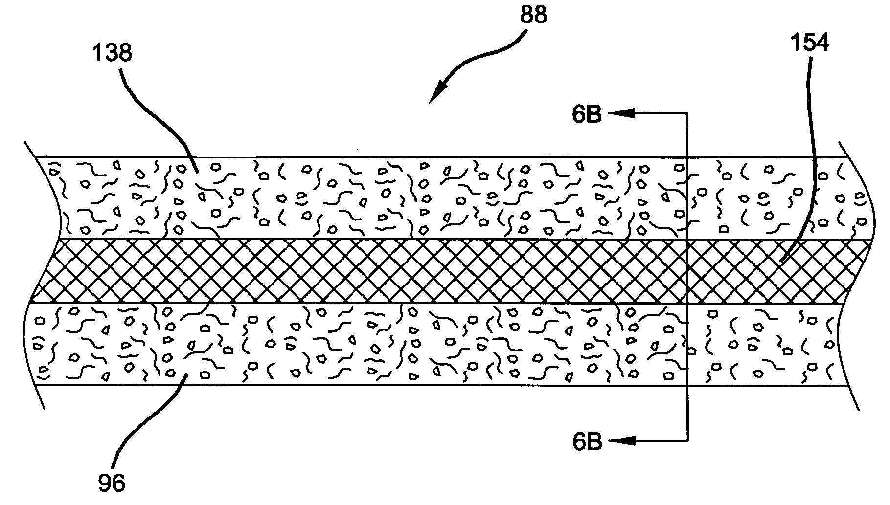
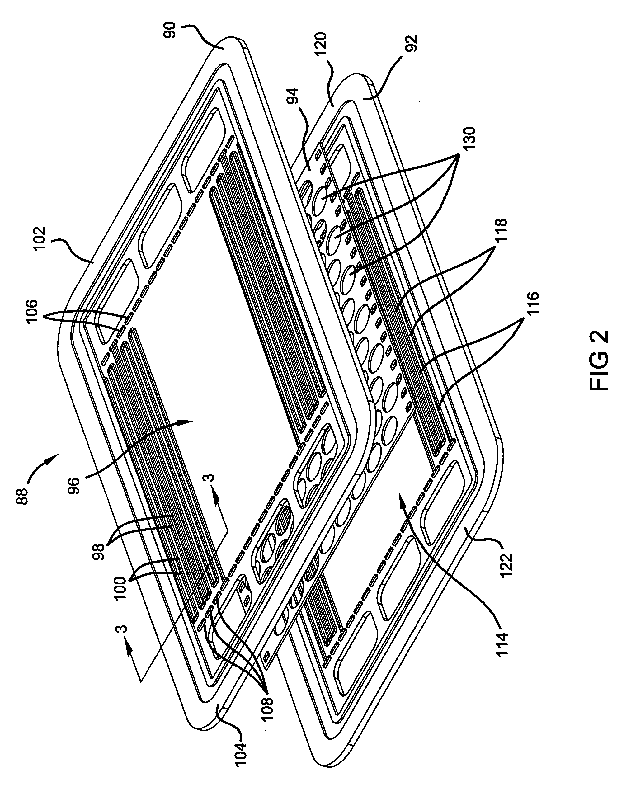
[0042] Thus, the present invention allows bipolar plates 88 to be economically and efficiently produced by using pre-c...


PUM

PropertyMeasurementUnit
thicknessaaaaaaaaaa
thicknessaaaaaaaaaa
thicknessaaaaaaaaaa

Abstract

The present invention discloses a method of efficiently manufacturing fuel cells having coated bipolar plates. The present invention contemplates the laser welding together of individual plates already having a coating thereon to form the bipolar plates that are used in a fuel cell. The laser welding of the coated plates together does not result in sensitization of the plates to a magnitude sufficient to cause an undesirable level of corrosion resistance. This result is achieved regardless of the presence of the organic coating in the region of the plates being welded and regardless of the ablating of the organic coating by the laser beam.

Description

FIELD OF THE INVENTION [0001] The present invention relates to fuel cells and more particularly to coated metallic plates that are laser welded together to form a bipolar plate of a fuel cell. BACKGROUND OF THE INVENTION [0002] Fuel cells have been proposed as a power source for electric vehicles and other applications. One known fuel cell is the PEM (i.e., Proton Exchange Membrane) fuel cell that includes a so-called MEA (“membrane-electrode-assembly”) comprising a thin, solid polymer membrane-electrolyte having an anode on one face and a cathode on the opposite face. The anode and cathode typically comprise finely divided carbon particles, very finely divided catalytic particles supported on the internal and external surfaces of the carbon particles, and proton conductive material intermingled with the catalytic and carbon particles. The MEA is sandwiched between a pair of electrically conductive contact elements which serve as current collectors for the anode and cathode, which m...

Claims


Application Information

Patent Timeline
Patent Type & Authority Applications(United States)
IPC IPC(8): B23K26/24B23K26/32H01M8/02H01M8/10H01M8/24
CPCB23K26/3206B23K26/3213B23K26/3226B23K26/3293H01M8/0206H01M8/021Y02E60/50H01M8/0228H01M8/0267H01M8/0297H01M8/241H01M2008/1095H01M8/0223B23K26/32B23K2101/34B23K2103/08B23K2103/50Y02P70/50H01M8/2483H01M8/2404H01M8/0263
Inventor NEWMAN, KEITH E.BUDINSKI, MICHAEL K.BRADY, BRIAN K.
Owner GM GLOBAL TECH OPERATIONS LLC
Learn More