

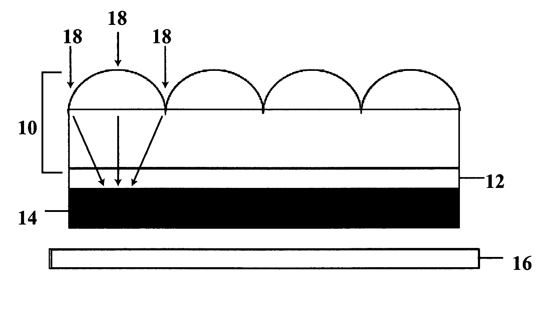
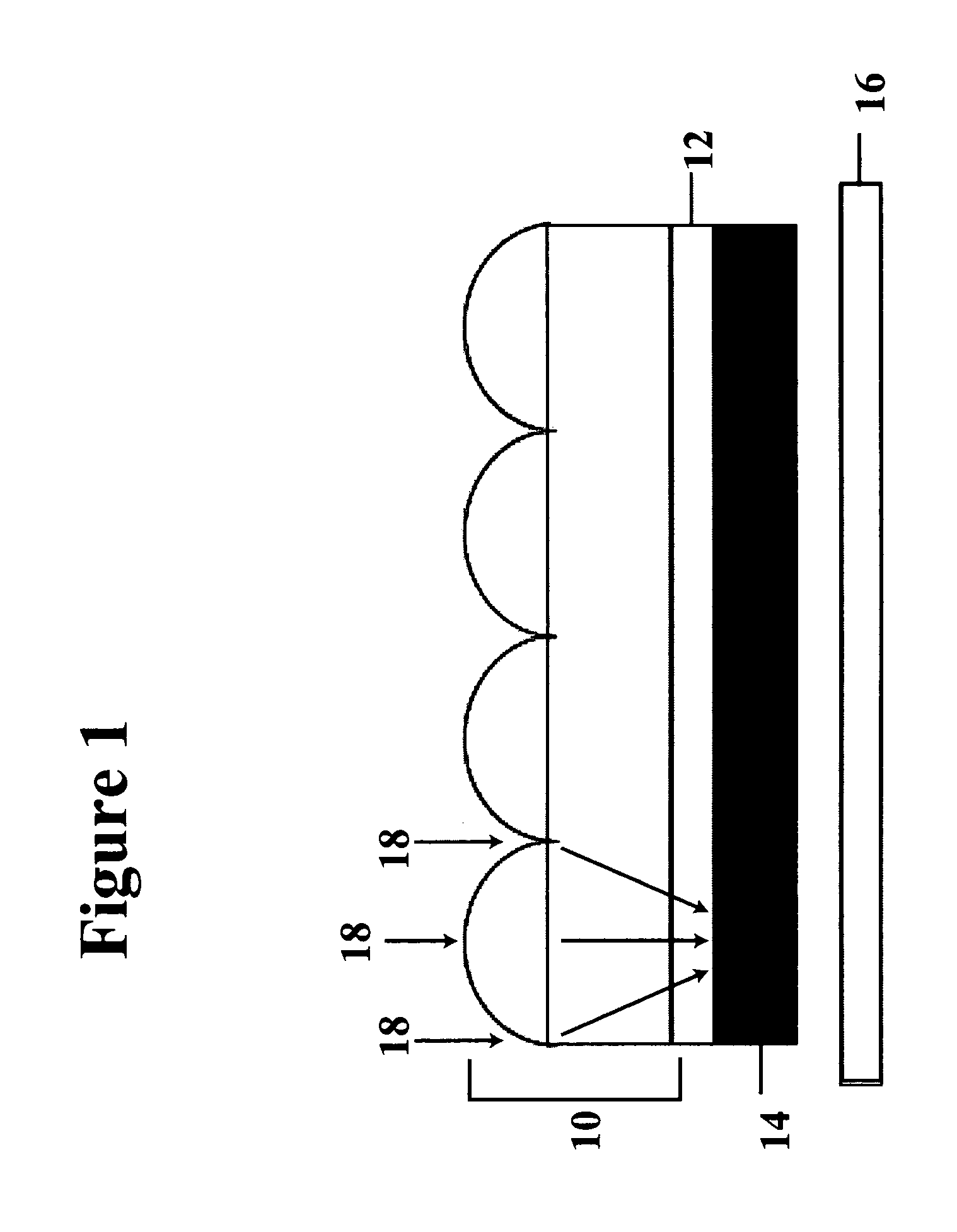
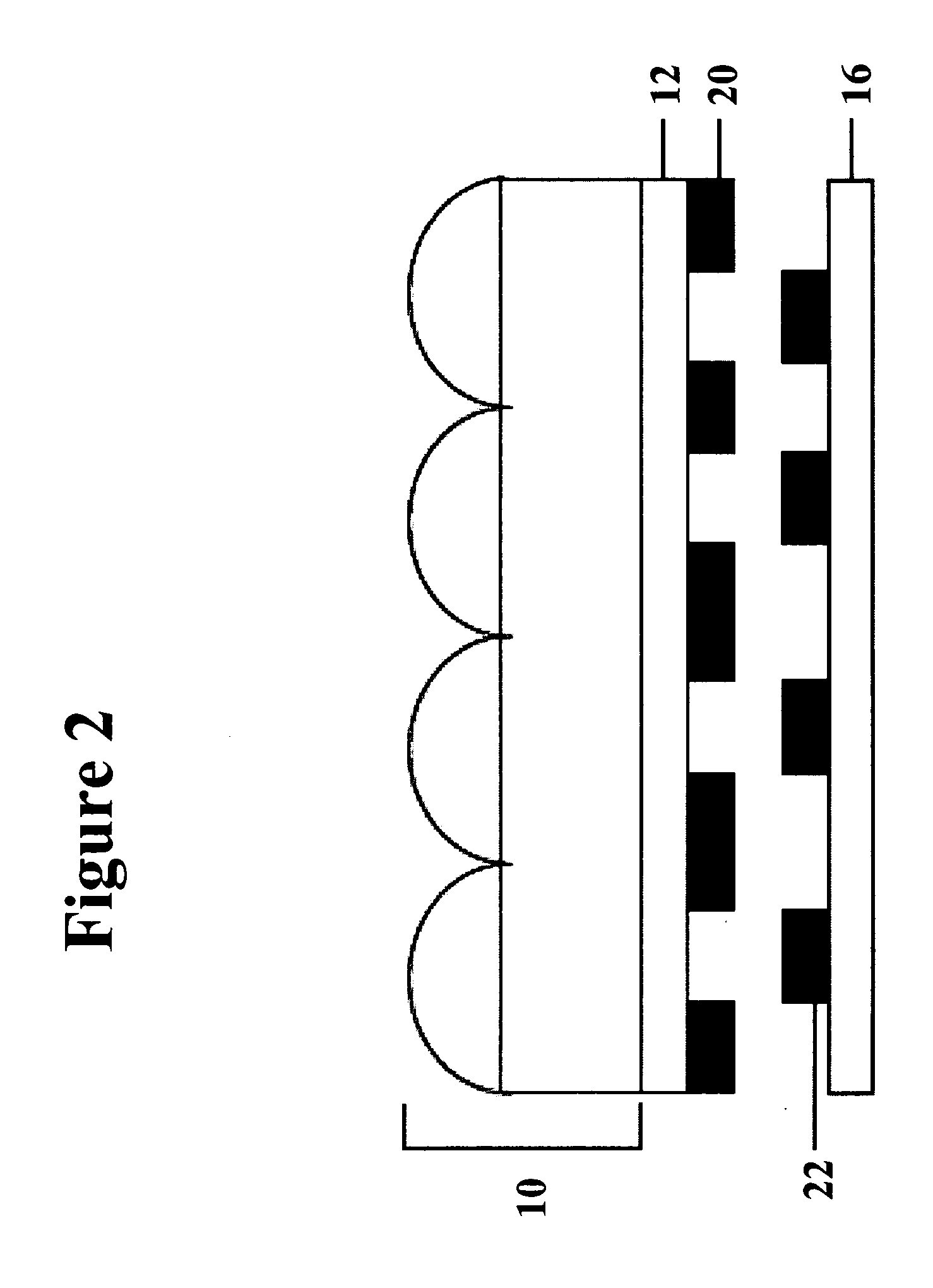
Methods for producing a black matrix on a lenticular lens
a technology of lenticular lens and black matrix, which is applied in the field of black matrix production on lenticular lens, can solve the problems of reducing distortion of the image seen on the lenticular lens, and redirected light, and achieves the effects of reducing the distortion of the image, reducing the distortion, and improving the quality of the imag
- Summary
- Abstract
- Description
- Claims
- Application Information
AI Technical Summary
Benefits of technology
Problems solved by technology
Method used
Image

Examples
example 1
[0100] In this example, an opaque matrix was formed using an infrared radiation sensitive material and a barrier layer that contained nitrocellulose and an infrared dye.
[0101] A barrier layer solution was prepared by mixing 88.4 wt.-% Cellulose Nitrate, 11.6 wt.-% PC 364 IR dye, and 0.03 wt.-% FC 4432 as a 4.8% total solids solution in a 4.5:1 solvent mix of methyl ethyl ketone and Solvent PM.
[0102] A black composition was prepared by mixing the components listed in Table 1 with coating aid FC 55 / 35 / 10 to create a 11.5% total solids solution in a 60:20:20 solvent blend of methyl ethyl ketone, Solvent PM, and ethanol alcohol.
[0103] To prepare the assembly, the flat surface of a lenticular lens was first coated with the barrier layer solution using a #11 wound wire rod and dried for 5 minutes at 190° F. to form a barrier layer. The lenticular lens contained parallel cylindrical lenticulae with a lens pitch of 0.146 mm. The black composition was then coated on the barrier layer usin...
example 2
[0107] In this example, an opaque matrix was formed using an infrared radiation sensitive material and a barrier layer that contained a polyvinyl alcohol and a crosslinking agent, but no infrared dye.
[0108] A barrier layer solution was prepared by mixing 81.6 wt.-% PVA 523, 18.0 wt.-% Glyoxal, and 0.4 wt.-% TRITON X-100 as a 2.5% total solids solution in a 75:25 solvent mix of water and n-propyl alcohol.
[0109] A black composition was prepared by mixing the components listed in Table 2 with coating aid FC 55 / 35 / 10 to create a 11.5% total solids solution in a 60:20:20 solvent blend of methyl ethyl ketone, Solvent PM, and ethanol alcohol.
[0110] To prepare the assembly, the flat surface of a lenticular lens was first coated with the barrier layer solution using a #11 wound wire rod and dried for 5 minutes at 190° F. to form a barrier layer. The lenticular lens contained parallel cylindrical lenticulae with a lens pitch of 0.146 mm. The black composition was then coated on the barrier...
example 3
[0114] In this example, an opaque matrix was formed using an infrared radiation sensitive material and a barrier layer containing nitrocellulose, but no crosslinking agent or infrared dye.
[0115] A barrier layer solution was prepared by mixing 99.97 wt.-% Cellulose Nitrate, and 0.03 wt.-% FC 4432 as a 4.8% total solids solution in a 4.5:1 solvent mix of methyl ethyl ketone and Solvent PM.
[0116] A black composition was prepared with the components contained in Table 3, in the same manner as the black composition used in Example 1.
[0117] To prepare the assembly, the flat surface of a lenticular lens was first coated with the barrier layer solution using a #11 wound wire rod and dried for 5 minutes at 190° F. to form a barrier layer. The lenticular lens had the same properties and dimensions as the lenticular lens used in Example 1. The black composition was then coated on the barrier layer using a #11 wound wire rod. The resulting assembly was dried for 3 minutes at 190° F. The blac...
PUM
 Abstract
Description
Claims
Application Information