Loop-tip catheter

a catheter and loop-tip technology, applied in the field of multi-lumen catheters, can solve the problems of blood clotting, loss of catheter function, and lower the efficiency of a dialysis procedure, and achieve the effects of preventing arterial suction, maximizing flow performance, and preventing fibrin formation

Inactive Publication Date: 2005-11-24
CR BARD INC
View PDF20 Cites 154 Cited by
  • Summary
  • Abstract
  • Description
  • Claims
  • Application Information

AI Technical Summary

Benefits of technology

[0007] Accordingly, a multi-lumen catheter (e.g., a dialysis catheter) is described, which addresses one or more of the common catheter design issues, such as flow performance, insertion ease, and longevity issues. One variation of the multi-lumen catheter includes a unique design on the distal end thereof, which will protect the arterial inlet and prevent sidewall occlusion. Another variation of the multi-lumen catheter has a catheter body that houses wires, mandrels or balloons to improve patency. The distal portion of such a catheter can be configured such that it is atraumatic to the vessel walls, and capable of minimizing recirculation rates. Another variation of the multi-lumen catheter can be easily manufactured. Another variation of the multi-lumen catheter provides resistance to fibrin sheath formation and / or is configured such that fibrin sheath removal is possible without removing the catheter from its implanted location. Still another variation of the multi-lumen catheter is introduced into a vessel with minimal risk of air embolism. Another variation of the multi-lumen catheter allows the user to seal the arterial inlet between dialysis sessions.
[0008] In one aspect of the invention, the tip of the catheter incorporates a loop-like structure. The catheter can be a single lumen catheter or includes a plurality of lumens. In one variation, the loop structure is designed to mechanically separate the channel outlets / inlets at the tip of the multi-lumen catheter to minimize vessel trauma, to protect the arterial inlet and to prevent sidewall occlusion. In another variation, a displacement mechanism is provided within the distal portion of the catheter for actively breaking or removing deposits (e.g., fibrin sheath, clots, etc.) from the distal end of the catheter. For example, a wire or mandrel can be embedded within the catheter for twisting or displacing the distal portion of the loop-tip catheter. In another example, a balloon is positioned within the loop structure at the distal portion of the catheter for expanding the tip of the catheter. The displacement mechanism may also be implemented for reconfiguring the catheter tip structure to protect a lumen opening on the loop structure. Wires, mandrels, balloons, etc., may also be utilized to improve patency, and / or to minimize recirculation. Furthermore, the loop structure may be flattened, compressed, contracted, or otherwise reduced in size to facilitate placement within an introducer sheath for introduction into the patient's circulatory system. The contraction of the distal loop-tip may also reduce the risk of air embolism.
[0010] The loop-tip can be designed with various configurations. For example, one configuration of the loop-tip design permits the placement of two single lumen catheters as a coupled unit, without the need to place the catheters separately. The bowed / looped tip may prevent arterial suction and acts to ensure that the side holes are oriented appropriately to maximize flow performance. Moreover, the tip may prevent fibrin formation due to its dynamic movement during dialysis procedures. The loop-tip can be configured to facilitate an “over-the-guidewire” placement, and can also be coil reinforced to improve kink and pinch resistance.
[0011] To facilitate insertion, one variation is provided with a disposable mandrel for insertion into the catheter lumen to straighten the tip, resulting in a flattening of the loop configuration. Another configuration of the loop-tip design places the arterial and / or venous inlet / exit sites along the length of the loop. The inlet / exit sites may be positioned in locations within the central vein (ie., superior vena cava (SVC) or right atrium) that may improve the efficiency of the dialyses process. To minimize recirculation, the arterial and venous openings may be formed on different sides of the loop-tip and / or may be staggered along the length thereof.

Problems solved by technology

The primary problems occurring in dual lumen dialysis catheters are blood clotting (thrombosis) and fibrin (the protein formed during normal blood clotting that is the essence of the clot) sheath formation.
Thrombus and fibrin sheath formation can occlude distal tips of the dialysis catheter lumens, resulting in loss of catheter function when such an occlusion prevents blood flow.
Other common problems related to dual lumen dialysis catheters include, (1) the arterial lumen “sucking” against the vessel wall, in which the arterial lumen openings become fully occluded by the patient's vasculature, and (2) recirculation of cleansed blood, which necessarily lowers the efficiency of a dialysis procedure.

Method used


Image

  • Loop-tip catheter
  • Loop-tip catheter
  • Loop-tip catheter

Examples


Embodiment Construction

in conjunction with the accompanying drawings that are first briefly described.

BRIEF DESCRIPTION OF THE DRAWINGS

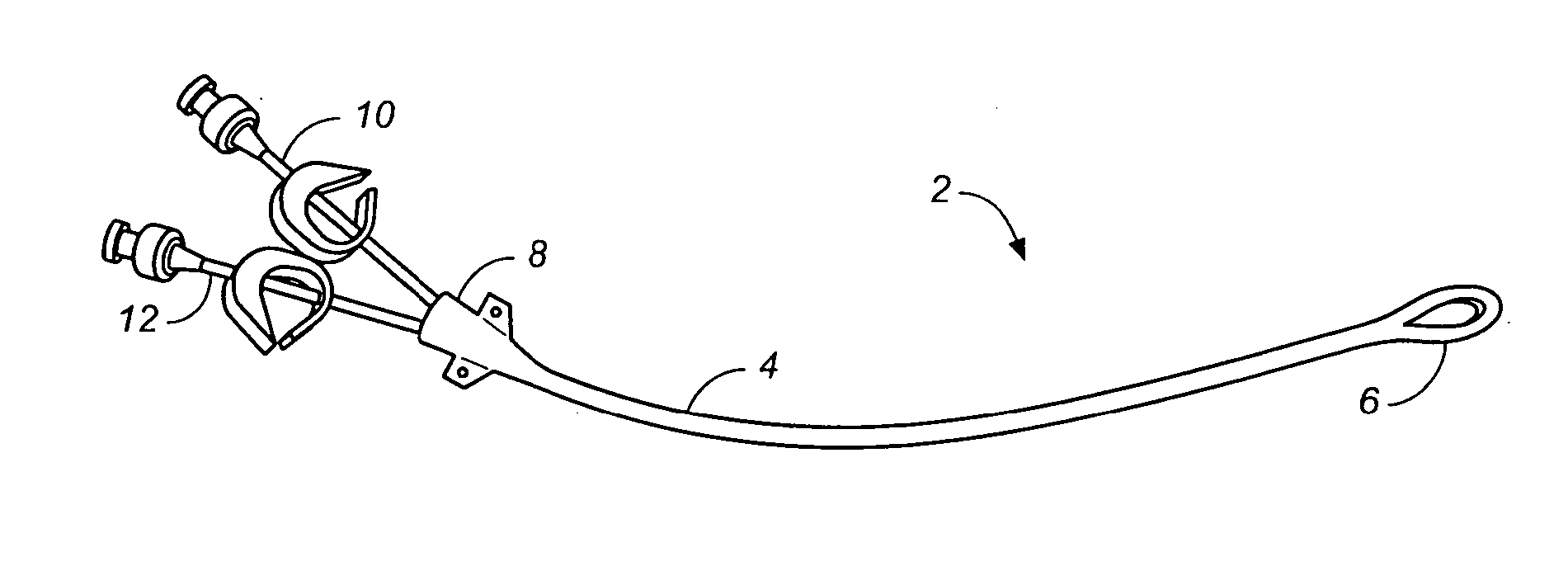
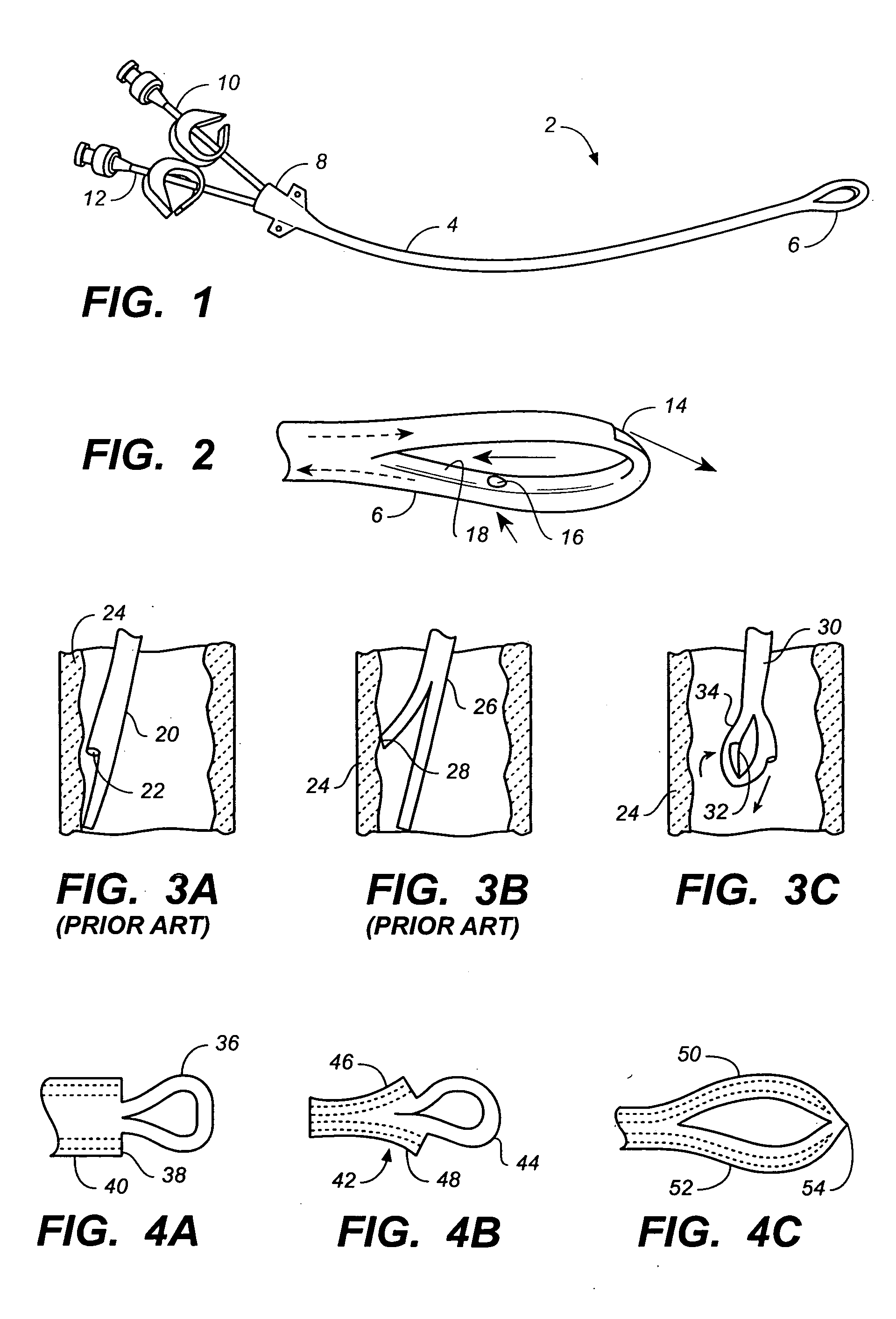
[0013]FIG. 1 illustrates one variation of a dual lumen loop-tip catheter.

[0014]FIG. 2 is an expanded view of the distal portion of the loop-tip catheter of FIG. 1. The arrows illustrate the direction of fluid flow for one possible application, where the catheter is utilized for hemodialysis.

[0015]FIG. 3A illustrates a typical hemodialysis catheter with staggered lumen openings suctioning against the wall of a blood vessel.

[0016]FIG. 3B illustrates a typical slip-tip hemodialysis catheter suctioning against the wall of a blood vessel.

[0017]FIG. 3C illustrates one variation of a loop-tip catheter utilized in a blood vessel for hemodialysis application. The loop structure prevents the arterial inlet from suctioning against the vessel wall.

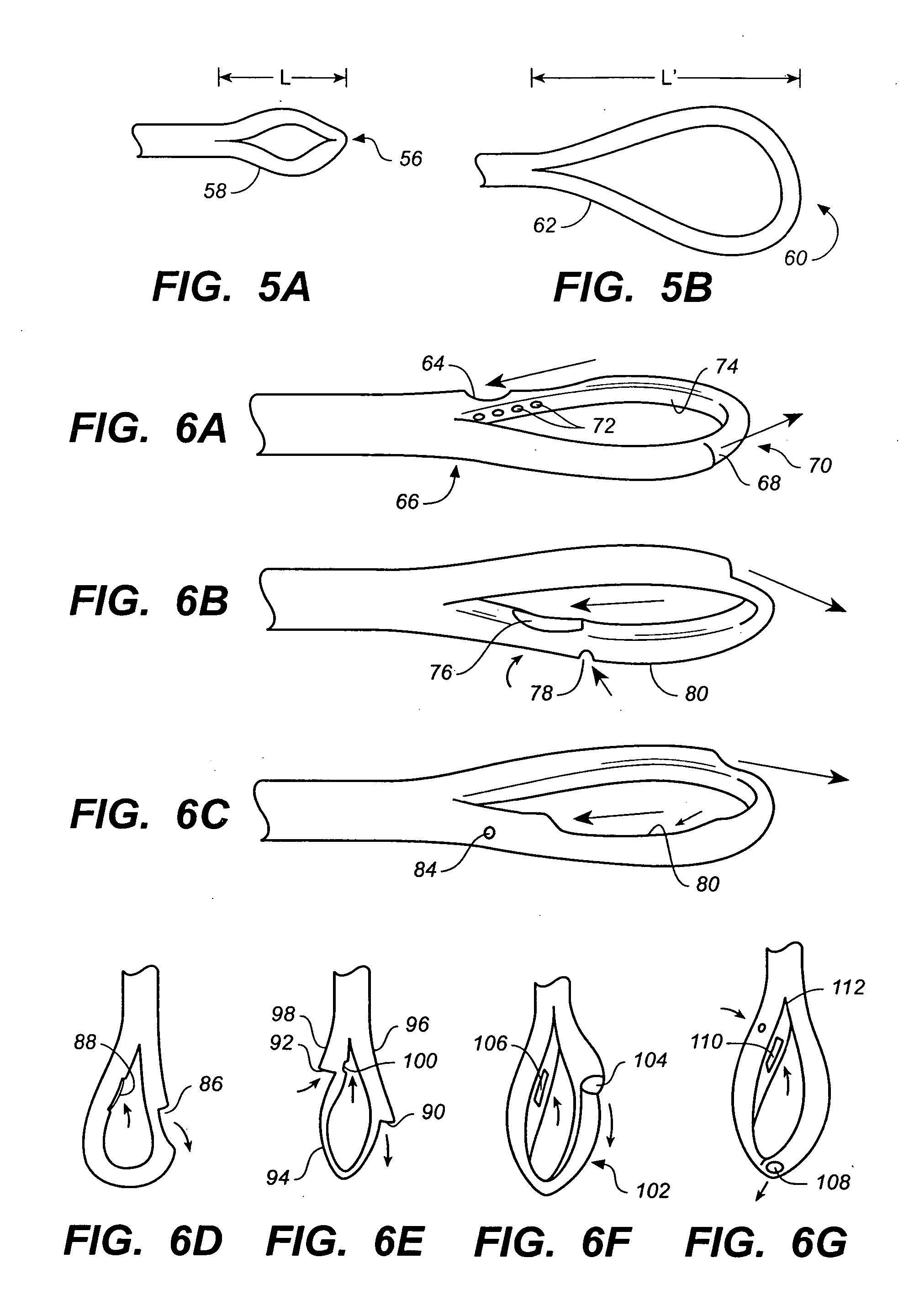
[0018]FIGS. 4A-4B illustrates various examples of loop-tip configurations. In FIG. 4A one variation including a loop extending distal...


PUM

PropertyMeasurementUnit
wall thicknessaaaaaaaaaa
inner diameteraaaaaaaaaa

Abstract

A multi-lumen catheter comprising a loop-like structure at the distal portion of the catheter is disclosed herein. In one variation, the loop-tip catheter comprises a dual lumen catheter and a loop-like structure at the distal end of the catheter. The loop-like structure includes at least one lumen, which is in fluid communication with at lease one of the two lumens in the dual lumen catheter. One or more ports are provided on the loop-like structure for accessing the lumens within the loop. In another variation, the loop-tip catheter is configured with an arterial inlet positioned on an inner surface of the loop, while a venous outlet is positioned on an outer surface of the loop. Methods for making and using variations of the loop-tip catheter are also disclosed herein.

Description

A CROSS-REFERENCE TO RELATED APPLICATIONS [0001] This application claims the benefit of U.S. provisional application No. 60 / 549,688 entitled “LOOP-TIP CATHETER” filed on Mar. 3, 2004, which is incorporated herein by reference in its entirety.STATEMENT REGARDING FEDERALLY SPONSORED RESEARCH OR DEVELOPMENT [0002] Not applicable. REFERENCE TO A COMPACT DISK APPENDIX [0003] Not applicable. BACKGROUND OF THE INVENTION [0004] Multi-lumen catheters are used for the purpose of creating two or more separate fluid pathways, such as in hemodialysis applications. A primary goal of hemodialysis access is to provide a reliable and effective means of dialysis, which means that a sufficient volume of blood over a period of time must be removed from and returned to the patient. Because the contaminated and cleansed blood must be kept separate for an effective dialysis procedure, a dual lumen catheter is generally used. These dual lumen catheters are usually configured so that there is a shorter lume...

Claims


Application Information

Patent Timeline
Patent Type & Authority Applications(United States)
IPC IPC(8): A61M25/00
CPCA61M2025/0034A61M2025/0031A61M25/0075A61M25/008A61M25/0074A61M2025/0037A61M25/0041A61M25/007A61M25/0068A61M25/003
Inventor PATTERSON, RYAN C.POWERS, KELLY B.ZAWACKI, JOHN A.MOEHLE, RYAN T.KRAUS, JEFF
Owner CR BARD INC
Why Eureka
Try Eureka