Measuring particulate matter in a fluid

a technology of particulate matter and fluid, which is applied in the direction of measurement devices, instruments, bundled fibre light guides, etc., can solve the problems of affecting the accuracy of measurement results, so as to achieve accurate measurement of particulate properties.

Active Publication Date: 2005-12-01
TELEDYNE
View PDF11 Cites 14 Cited by
  • Summary
  • Abstract
  • Description
  • Claims
  • Application Information

AI Technical Summary

Benefits of technology

[0011] In one general respect, the present invention is directed to a device for measuring near forward scatter caused by particulate matter in a fluid. The device, according to various embodiments, comprises a transceiver and a reflector. The transceiver includes a light source and a detector. The light source may be selected depending on the wavelengths of light to be measured and the size of the particulate, which in combination may determine the efficiency of the scattering process at any particular angle. Further a variety of light sources with different wavelengths may be used to more accurately determine the properties of the particulate. The reflector is positioned opposite the transceiver so that at least a portion of the fluid is present between the transceiver and the reflector. The reflector includes a front portion facing the transceiver. Optical energy from the light source incident upon the reflector is reflected towards the transceiver as a return beam of optical energy that is shaped such that ideally none of the main projected beam impinges directly on the detector. The light reaching the detector may be primarily the light that is scattered from the returned beam over a range of near forward angles by particulate matter in the fluid.

Problems solved by technology

Power generation plants and other industrial facilities may release particulate matter into the atmosphere, especially if the facilities burn coal or other fossil fuels.
Because the particulate matter degrades air quality and reduces visibility (haze) governmental regulations require some facilities to continuously control and monitor their particulate matter emissions.
Although a number of techniques are available to measure the mass loading of particulate matter emissions directly, many are costly and incapable of reliable continuous operation under field conditions.
Extinction measurements are dependent on variables other than mass loading, thus reducing the accuracy of an extinction measurement as a predictor of particulate mass loading.
Extinction measurements may be unusable at very low particulate mass loadings as the extinction measurement becomes difficult to make with good accuracy.
Like extinction, however, backscatter techniques are very sensitive to the size, and shape of the particulate.
Existing devices for measuring near forward scatter are often complicated, expensive, and difficult to calibrate and maintain.
Many are point sampling or close coupled extractive devices and hence introduce measurement errors in applications with significant particulate stratification.
Existing devices are also unable to take advantage of the strengths of other known techniques, for example extinction and backscatter.

Method used


Image

  • Measuring particulate matter in a fluid
  • Measuring particulate matter in a fluid
  • Measuring particulate matter in a fluid

Examples


Embodiment Construction

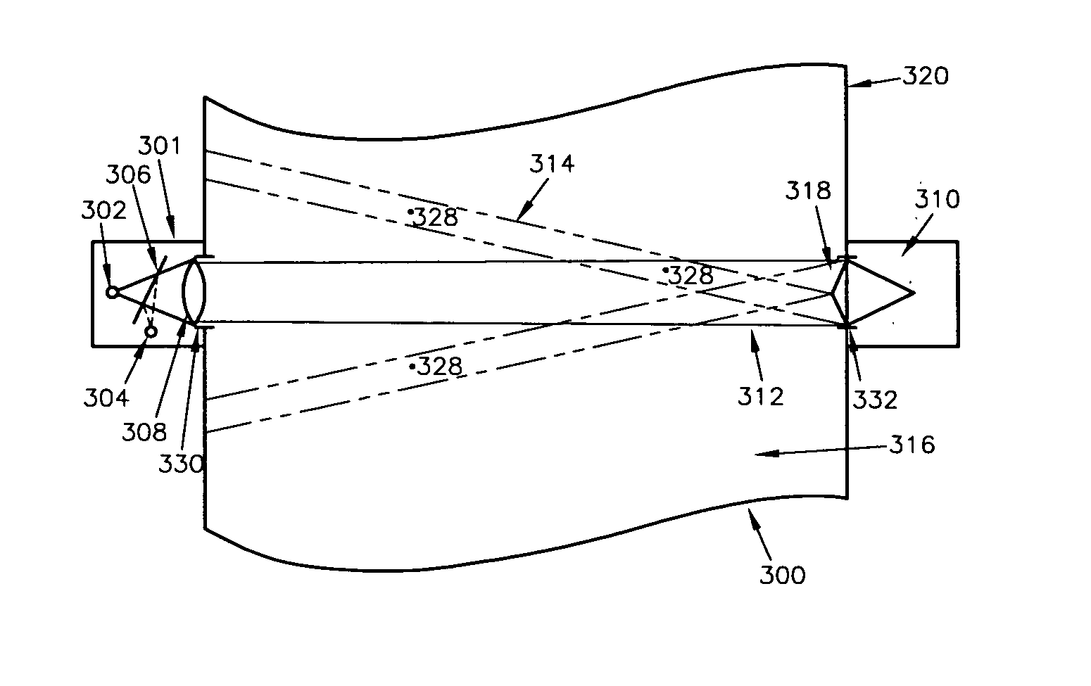
[0024]FIGS. 3, 3A and 4 depict a device 300 for measuring near forward scatter caused by particulates 328 in a fluid 316 according to various embodiments of the present invention. The device 300 may include a transceiver 301 and a reflector 310. The transceiver 301 may include a light source 302, a detector 304, a beam splitter 306 and a lens 308. The light source 302 may be any device capable of projecting a light beam such as, for example, a light emitting diode (LED), a diode or gas laser, or an incandescent source. According to one embodiment, a green LED may be used as the light source 302. The wavelength of the light source 302 may be determined based on the size of the particulates to be measured. Also, according to various aspects, the device 300 may contain more than one light source to measure scattered optical energy at multiple wavelengths. The detector 304 may be a photodiode or any other device capable of sensing optical energy reflected from the reflector 310 at a sma...


PUM

PropertyMeasurementUnit
near forward anglesaaaaaaaaaa
wavelengthsaaaaaaaaaa

Abstract

A device for measuring near forward scatter caused by particulate matter in a fluid is disclosed. The device comprises, according to various embodiments, a transceiver and a reflector. The transceiver includes a light source and a detector. The reflector is positioned opposite the transceiver so that at least a portion of the fluid is present between the transceiver and the reflector. The reflector includes a front portion facing the transceiver. Optical energy from the light source incident upon the reflector is reflected towards the transceiver as a return beam of optical energy, wherein the detector senses primarily optical energy of the return beam that is scattered over a range of near forward angles by particulate matter in the fluid.

Description

BACKGROUND OF THE INVENTION [0001] The present invention is directed generally to the measurement of certain optical properties of the interaction of light with particulate matter in a fluid. [0002] Power generation plants and other industrial facilities may release particulate matter into the atmosphere, especially if the facilities burn coal or other fossil fuels. Particulate matter in the flue gases generated from the burning of coal tends to be mostly spherical, solidified droplets of a variety of sizes from the metallic components of the ash in the coal. Because the particulate matter degrades air quality and reduces visibility (haze) governmental regulations require some facilities to continuously control and monitor their particulate matter emissions. Particulate mass emission rates are reported in units of weight per time (tons / yr), and are determined from particulate mass loading measurements in wt / volume (grains / standard cubic foot) and a corresponding measure of stack gas...

Claims


Application Information

Patent Timeline
Patent Type & Authority Applications(United States)
IPC IPC(8): G01N21/00G01N21/53G02B6/04
CPCG01N2021/4707G01N21/53
Inventor MYERS, RICHARDMCCALL, EDWARD L.MCGOWAN, GERALD F.SMIERCIAK, EDWARD A.
Owner TELEDYNE
Why Eureka
Try Eureka