
Communication channel calibration with nonvolatile parameter store for recovery

a communication channel and parameter storage technology, applied in the direction of synchronisation signal speed/phase control, instruments, transmission monitoring, etc., can solve the problems of large initialization process time consumption, system and environmental conditions will change, and brute force calibration routines are long, so as to achieve the effect of communicating data very quickly

Active Publication Date: 2005-12-01
RAMBUS INC
View PDF86 Cites 43 Cited by
  • Summary
  • Abstract
  • Description
  • Claims
  • Application Information

AI Technical Summary

Benefits of technology

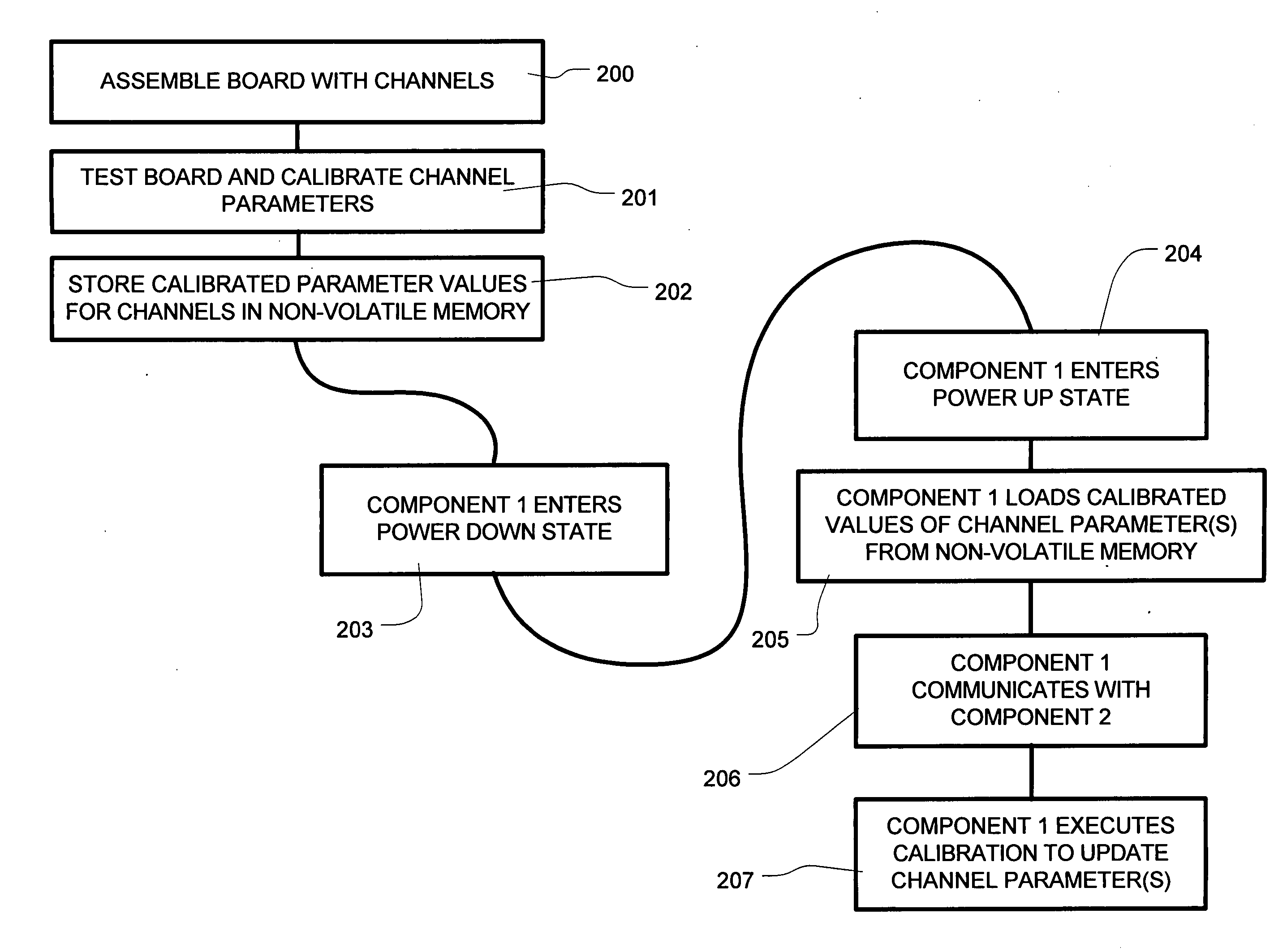
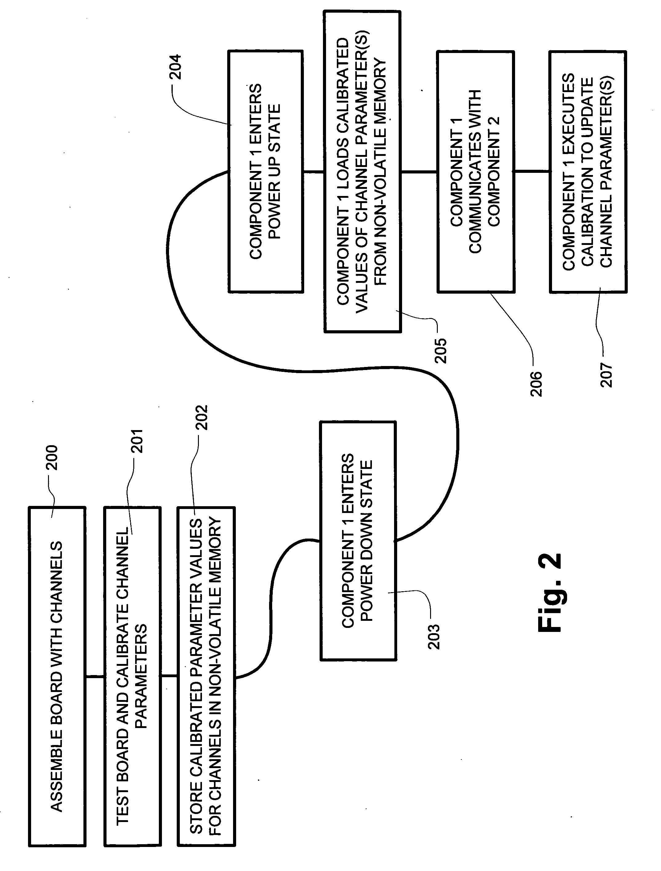
[0010] The present invention provides a method for calibrating a communication channel coupling first and second components during restart operations which occur for example after power down events. According to the method, after assembly of a communication channel, upon power up a calibration process is executed to determine one or more calibrated parameter values for the communication channel. The calibrated parameter values are then stored in nonvolatile memory, which is accessible by at least one of the first and second components, where nonvolatile memory is provided by a memory device or other storage that maintains data during power down events. Upon restarting the communication channel in the field, such as upon a power up event after a power management operation, or after other loss of power events, the procedure includes obtaining the calibrated parameter value in the nonvolatile memory, and setting an operating parameter of the communication channel using the calibrated parameter value. The communication channel is then enabled for communicating data very quickly, without requiring exhaustive calibration operations.

Problems solved by technology

However, during normal operation, system and environmental conditions will change.
Another problem arises during power down events, which occur under typical power loss scenarios, and increasingly under power management schemes that preserve battery power.
The recalibration process after loss of power presents a type of “chicken and egg” problem, where communication across the channel must take place before calibration.
These brute force calibration routines are lengthy, and consume a significant portion of time used by the initialization process after power down events.
The delay caused by the initialization process can be a significant factor in system performance.

Method used


Image

  • Communication channel calibration with nonvolatile parameter store for recovery
  • Communication channel calibration with nonvolatile parameter store for recovery
  • Communication channel calibration with nonvolatile parameter store for recovery

Examples


Embodiment Construction

[0035] A detailed description of embodiments of the present invention is provided with reference to the FIGS. 1-17.

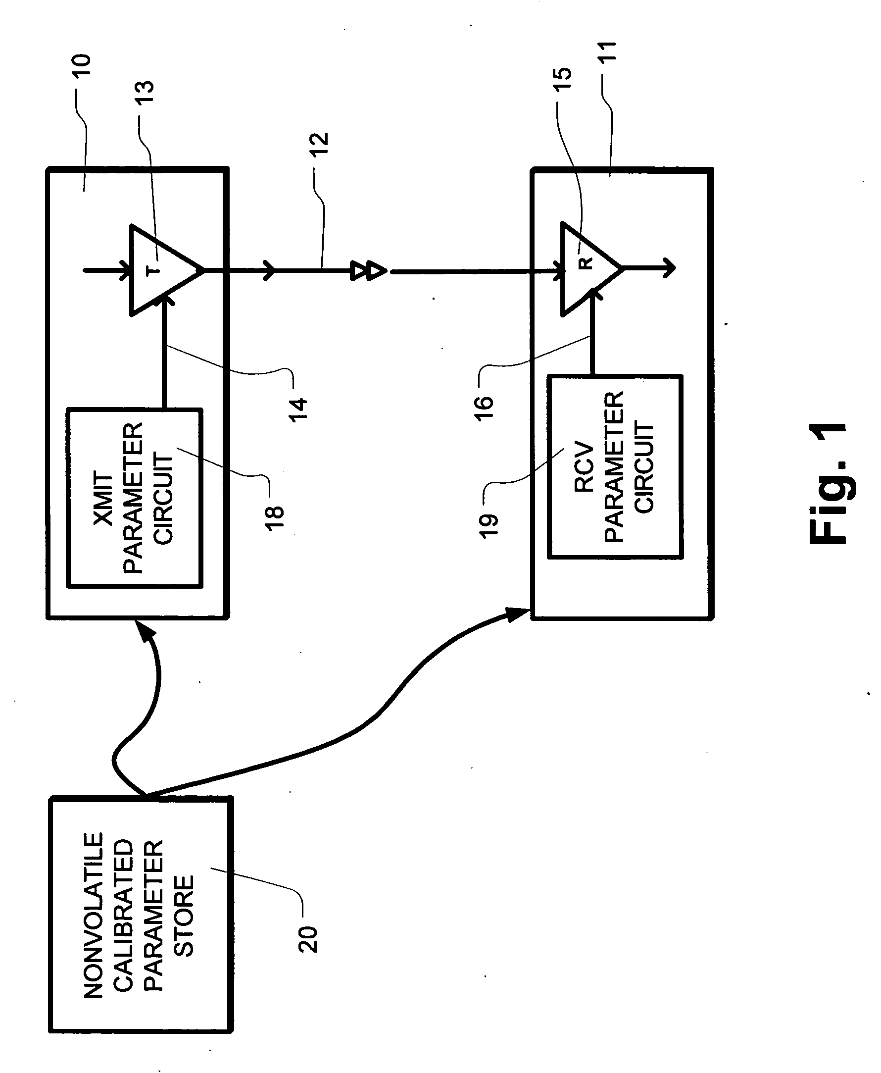
[0036]FIG. 1 illustrates in a simplified schematic form, a first component 10 which is coupled to a second component 11 by a communication channel which includes a transmitter 13 on the first component 10, a communication link 12, and a receiver 15 on the second component 11. A transmit parameter circuit 18 is included on the first component 10. Likewise a receive parameter circuit 19 is included on the second component 11. The transmit parameter circuit 18 is used to produce a transmit clock CLKT on line 14, which is connected to the transmitter 13. The receive parameter circuit 19 is used to produce a receive clock CLKR on line 16, which is connected to the receiver. A nonvolatile store 20 holding calibrated parameter values is coupled to the first component 10 and a second component 11. The first component 10, the communication link 12 and the second component 11 ar...


PUM


Abstract

A communication channel is operated by storing a calibrated parameter value in nonvolatile memory during manufacturing, testing, or during a first operation of the device. Upon starting operation of the communication channel in the field, the calibrated parameter value is obtained from the nonvolatile memory, and used in applying an operating parameter of the communication channel. After applying the operating parameter, communication is initiated on a communication channel. The operating parameter can be adjusted to account for drift immediately after starting up, or periodically. The process of starting operation in the field includes power up events after a power management operation. In embodiments where one component includes memory, steps can be taken prior to a power management operation using the communication channel, such as transferring calibration patterns to be used in calibration procedures.

Description

BACKGROUND OF THE INVENTION [0001] 1. Field of the Invention [0002] The present invention relates to calibration of communication channel parameters in systems, including mesochronous systems, in which two (or more) components communicate via an interconnection link; and to calibration to account for drift of conditions related to such parameters during operation of the communication channels. [0003] 2. Description of Related Art [0004] In high-speed communication channels which are operated in a mesochronous manner, typically a reference clock provides frequency and phase information to the two or more components on the link. A transmitter on one component and a receiver on another component each connect to the link. The transmitter and receiver operate in different clock domains, which have an arbitrary (but fixed) phase relationship to the reference clock. The phase relationship between transmitter and receiver is chosen so that the propagation delay seen by a signal wavefront pa...

Claims


Application Information

Patent Timeline
Patent Type & Authority Applications(United States)
IPC IPC(8): G11C7/20G11C29/02H04B3/46H04L7/00H04L7/10
CPCG11C7/20G11C29/02G11C29/022G11C29/028H04L25/49H04L5/1438H04L7/0004H04L7/0091H04L7/10G11C2029/4402
Inventor YEUNG, PHILIPPEREGO, RICHARD E.BEST, SCOTT C.
Owner RAMBUS INC
Learn More