
Stirling cycle engine

Inactive Publication Date: 2005-12-08
TWINBIRD CORP
View PDF9 Cites 16 Cited by
  • Summary
  • Abstract
  • Description
  • Claims
  • Application Information

AI Technical Summary

Benefits of technology

[0007] The present invention has been made to solve the above problems. It is, therefore, an object of the present invention to simplify a structure of a Stirling cycle engine so as to simplify the assembling thereof and to enhance the abrasion resistance and lubricity of a cylinder, displacer and piston so as to improve the reliability of the Stirling cycle engine.
[0008] In order to attain the above object, according to a first aspect of the present invention, there is provided a Stirling cycle engine comprising: a casing; a cylinder coaxially inserted into the casing; a displacer slidably inserted into the inside of a distal portion of the cylinder; a piston slidably inserted into the inside of a proximal portion of the cylinder; and a driving mechanism provided at an outer periphery of the proximal portion of the cylinder, the driving mechanism reciprocating the piston, wherein either an inner peripheral surface of the cylinder or (an) inner peripheral surface(s) of the piston and / or displacer is made from an engineering plastic having fine abrasion resistance, dimensional stability, mechanical strength and formability.
[0009] By employing the above-described structure, the cylinder, piston, displacer etc. can have necessary abrasion resistance, precision and strength. Accordingly, reliability, durability and effectiveness of the Stirling cycle engine can be enhanced. Further, those cylinder, piston, displacer and, etc. can be simply made by a well-known plastic molding.

Problems solved by technology

In the case of using lubricating oil in order to improve the abrasion resistance and lubricity thereof, the lubricating oil may fly in all directions within the Stirling cycle engine, so that the flied lubricating oil may cause the regenerator to be clogged therewith, and thus the flow of the gas is blocked.
In the case of forming the gas lubrication mechanisms, however, since it is necessary to form gas-films by continuously blowing the gas inside the Stirling cycle engine to small clearances between the cylinder and the piston and / or displacer, the structures of the piston and / or displacer become complicated.
Accordingly, a complicated processing is necessary, and thus not only the cost thereof would be increased, but also the reliability thereof would be jeopardized.
Moreover, in the case of forming the PTFE coating, the PTFE on the surfaces may be abraded due to the movement of the piston and / or displacer in the cylinder even if it has self-lubricity, while the worn PTFE is liable to be reduced to powder and cause the regenerator to be clogged therewith.

Method used


Image

  • Stirling cycle engine
  • Stirling cycle engine
  • Stirling cycle engine

Examples


first embodiment

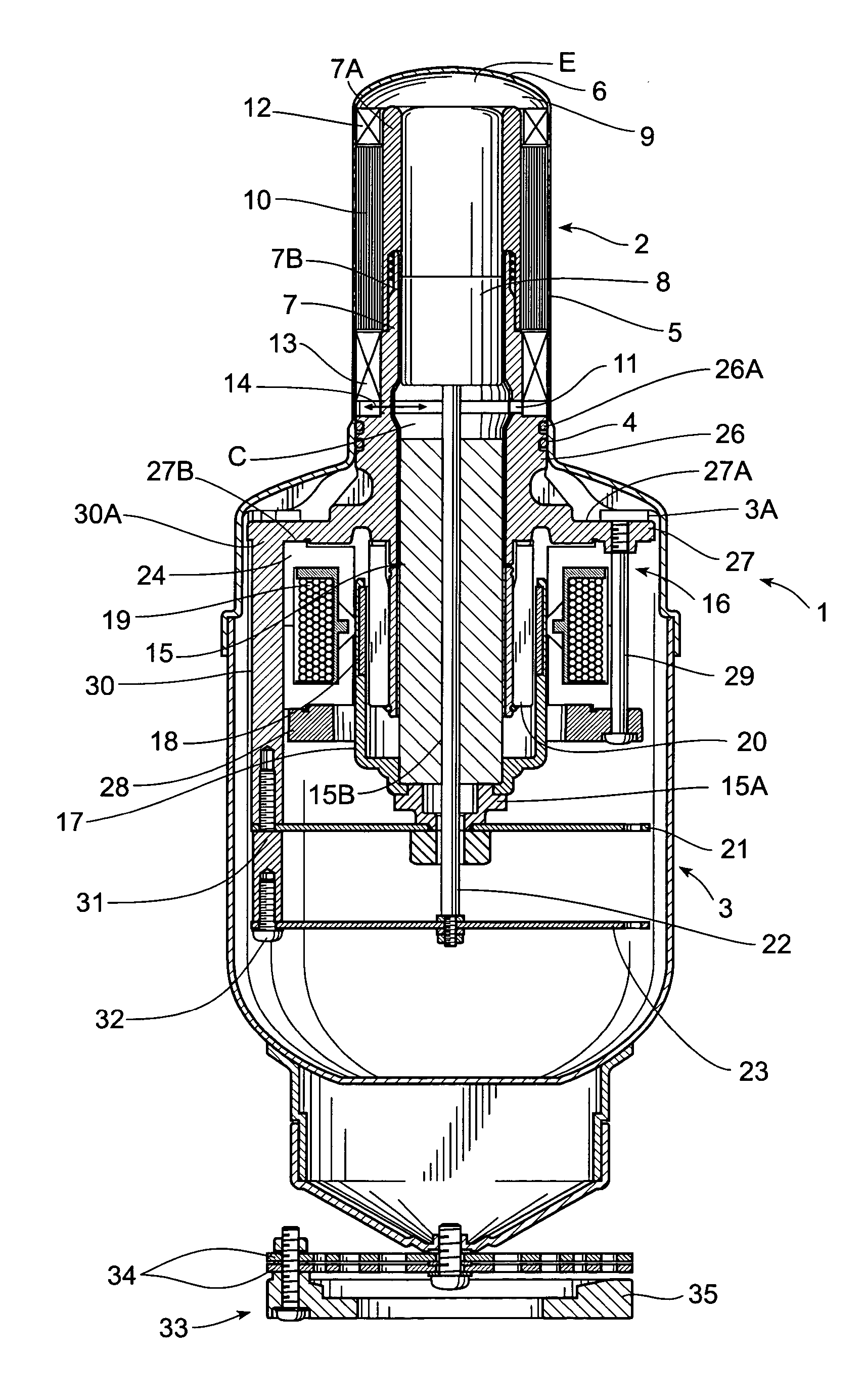
[0033] In FIG. 1, reference number 1 denotes a casing which comprises: a cylindrical portion 2 formed in a substantially cylindrical shape; and a main body portion 3 also formed in a substantially cylindrical shape. The cylindrical portion 2 is made from, for example, stainless steel and comprises a proximal portion 4, an intermediate portion 5 and a distal portion 6, while these three portions are integrated with one another.

[0034] Inside the cylindrical portion 2, a cylinder 7 extending to the inside of the main body portion 3 is coaxially inserted. An extended cylinder portion 7A which is a discrete portion from the cylinder 7 is coaxially connected to the distal end of the cylinder 7 adjacent to the distal portion 6. The cylinder 7 locating adjacent to the main body portion 3 is integrally formed with mounts 26, 27 (described later) and a plurality of connecting arms 30 (also described later) by casting such as die casting, using a metallic material such as aluminum, and the in...

second embodiment

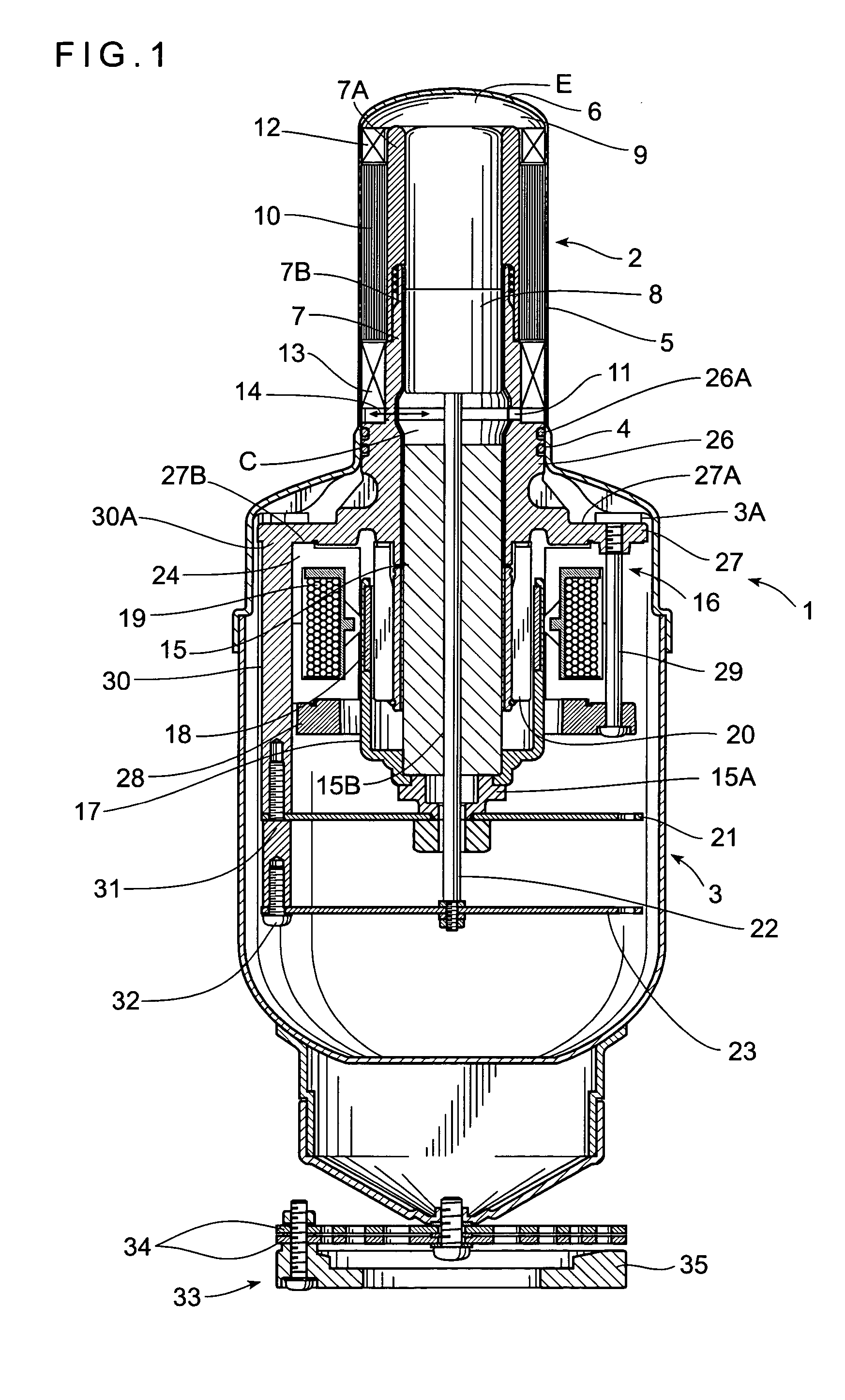
[0043] Next, a second embodiment of the present invention will now be described. FIG. 2 is a cross sectional view showing a part of a piston of a Stirling cycle engine according to the second embodiment. Meanwhile, the Stirling cycle engine of this embodiment employs the same structure as that of the first embodiment except a piston 36, and thus the same reference numbers will denote the same structural portions, and detailed explanations thereof will be omitted. In this embodiment, two grooves 37 are formed along the outer periphery of the piston 36 on the outer surface thereof, while piston rings 38 made from PPS are fitted in the grooves 37, and thus the piston rings 38 slide on the inner peripheral surface of the cylinder 7 when the piston 36 reciprocates. As with the first embodiment, PPS is an engineering plastic having fine mechanical strength and formability, accordingly dimensional stability, mechanical strength and abrasion resistance are further added by mixing discontinu...

third embodiment

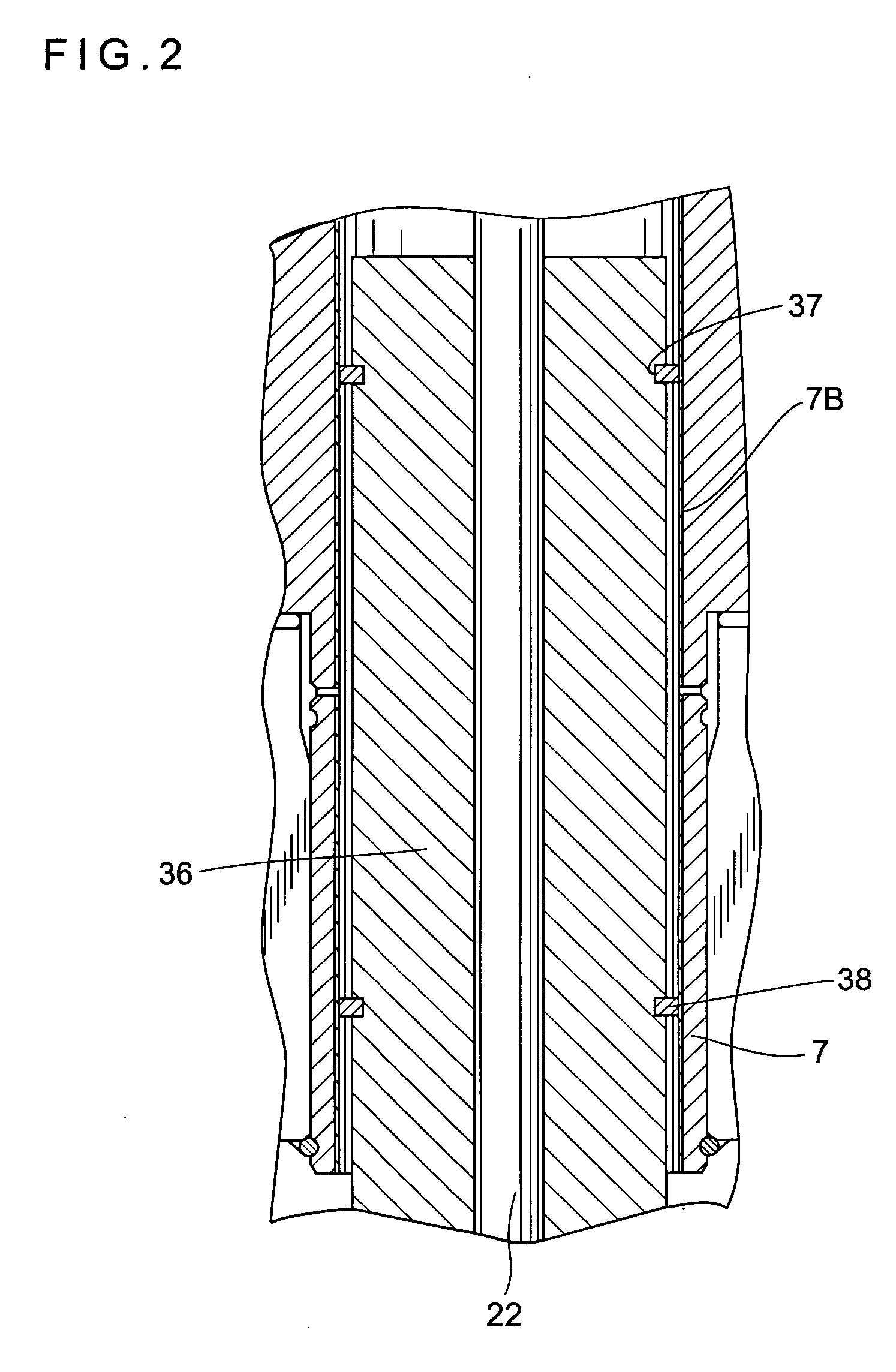
[0046] Next, a third embodiment of the present invention will now be described. FIG. 3 is a cross sectional view showing a part of a piston of a Stirling cycle engine according to the third embodiment. Meanwhile, the Stirling cycle engine of this embodiment employs the same structure as that of the first embodiment except a piston 39, and thus the same reference numbers will denote the same structural portions, and detailed explanations thereof will be omitted. In this embodiment, two sleeves 40 (sliding-contacting means) are passed through a rod-through-hole 39A of a piston 39, while the sleeves 40 and the rod 22 are to slide. The sleeves 40 are made from PPS, an engineering plastic having fine mechanical strength and formability, to which are added dimensional stability, mechanical strength and abrasion resistance by mixing discontinuous fibers of carbon, while lubricity is added by adding solid lubricity agent such as molybdenum disulfide, PTFE or the like.

[0047] According to th...


PUM


Abstract

A Stirling cycle engine of a simplified structure, having enhanced reliability by improving abrasion resistance and lubricity of components thereof. When a piston reciprocates in a cylinder along the axial direction thereof by a driving mechanism, a displacer reciprocates in the cylinder along the axial direction thereof accompanying the reciprocation of the piston. The piston and the displacer slide in contact with the inner peripheral surface of the cylinder, but the piston and the displacer are each integrally made from an engineering plastic such as PPS having fine strength, dimensional stability, abrasion resistance and formability, while PPS is made CFRP. Moreover, solid lubricity agent is added to PPS. Accordingly, abrasion resistance, lubricity, strength and precision of the piston and displacer are enhanced, while the piston and the displacer can be simply produced by a well-known plastic molding.

Description

BACKGROUND OF THE INVENTION [0001] 1. Field of the Invention [0002] The present invention relates to a Stirling cycle engine. [0003] 2. Description of the Related Art [0004] An example of a conventional Stirling cycle engine is disclosed in Japanese Patent Unexamined Publication No. 2001-355513. The disclosed Stirling cycle engine has a piston and a displacer slidably inserted into a cylinder provided within a casing, the piston being reciprocated by a driving mechanism. When the piston is operated by the driving mechanism so that it travels in the cylinder and comes close to the displacer, a gas, which is in a compression chamber provided between the piston and the displacer, is compressed and flows into an expansion chamber provided between a distal end of the displacer and a distal portion of the casing, through a heat dissipating fin, a regenerator and a heat absorbing fin. Accordingly, the displacer is pushed downwardly with a predetermined phase difference relative to the pist...

Claims


Application Information

Patent Timeline
IPC IPC(8): F02G1/044
CPCF02G1/044F02G2280/10F02G2258/50F02G2243/02
Inventor TAKAHASHI, TAKASHIURASAWA, HIDETO
Owner TWINBIRD CORP
Learn More