
Raised photodiode sensor to increase fill factor and quantum efficiency in scaled pixels

a photodiode and scaled pixel technology, applied in the field of digital image sensors, can solve the problems of reducing reducing the leakage and barrier problem, and cmos imagers that have difficulty transferring all of the photogenerated charge from the photodiode, so as to increase the quantum efficiency of the pixel cell, reduce the leakage and barrier problem, and reduce the leakage

Active Publication Date: 2005-12-08
MICRON TECH INC
View PDF4 Cites 39 Cited by
  • Summary
  • Abstract
  • Description
  • Claims
  • Application Information

AI Technical Summary

Benefits of technology

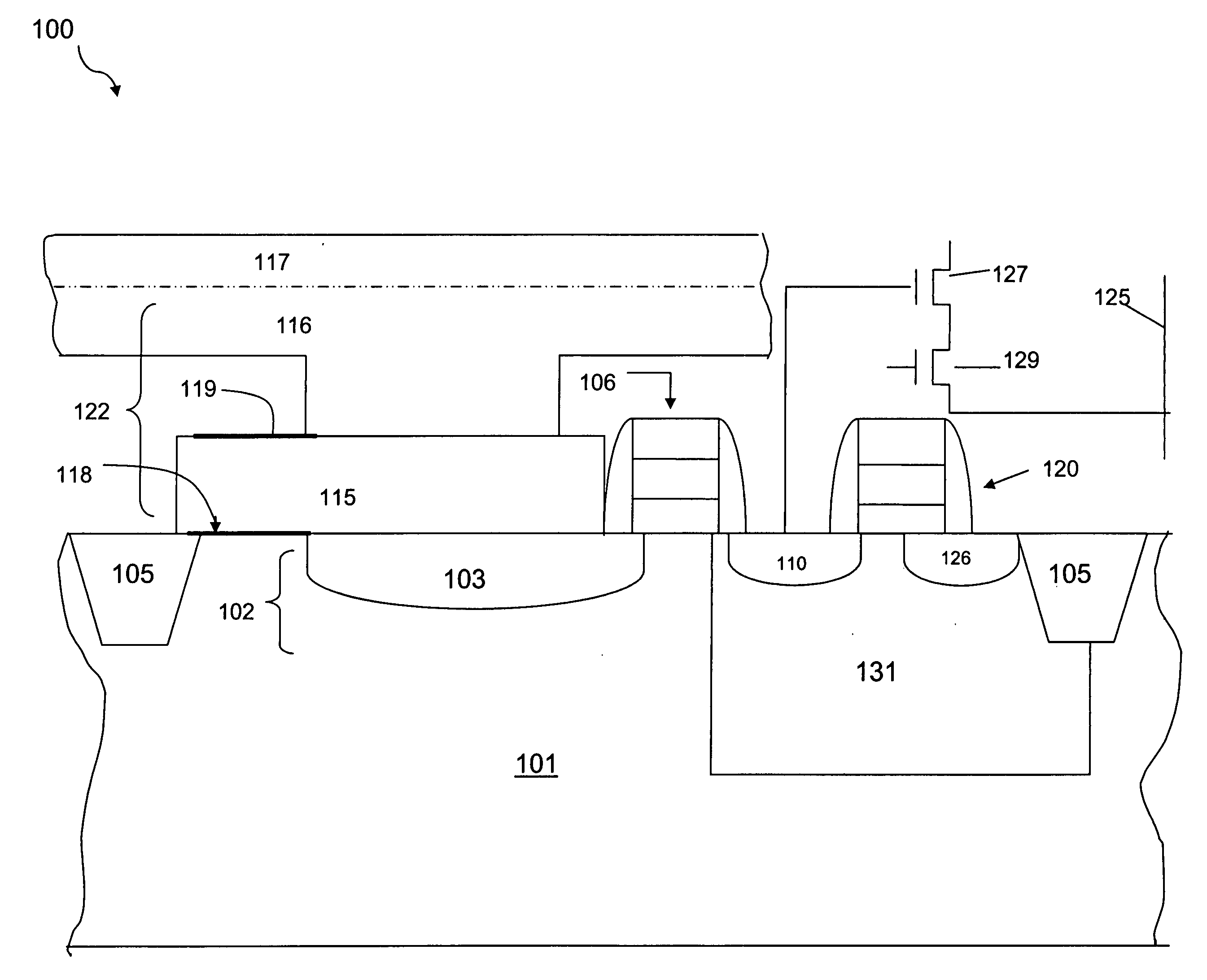
[0009] The present invention provides embodiments of image pixel cells with a doped, hydrogenated amorphous silicon photosensor, raised above the surface of a substrate. Methods of forming the raised photosensor are also disclosed. Raising the photosensor increases the fill factor and the quantum efficiency of the pixel cell. Utilizing hydrogenated amorphous silicon decreases the leakage and barrier problems of conventional photosensors, thereby increasing the quantum efficiency of the pixel cell. Moreover, the doping of the photodiode with inert implants like fluorine or deuterium further decreases leakage of charge carriers and mitigates undesirable hysteresis effects.

Problems solved by technology

Conventional CMOS imagers typically have difficulty transferring all of the photogenerated charge from the photodiode to the floating diffusion region.
One problem with transferring charge occurs when the n-type silicon layer of the photodiode is located close to the surface; this causes electron / carrier recombination due to surface defects.
Another obstacle hindering “complete” charge transference includes potential barriers that exist at the gate of a transfer transistor.
Additionally, conventional CMOS imager designs provide only approximately a fifty percent fill factor, meaning only half of the pixel is utilized in converting light to charge carriers.
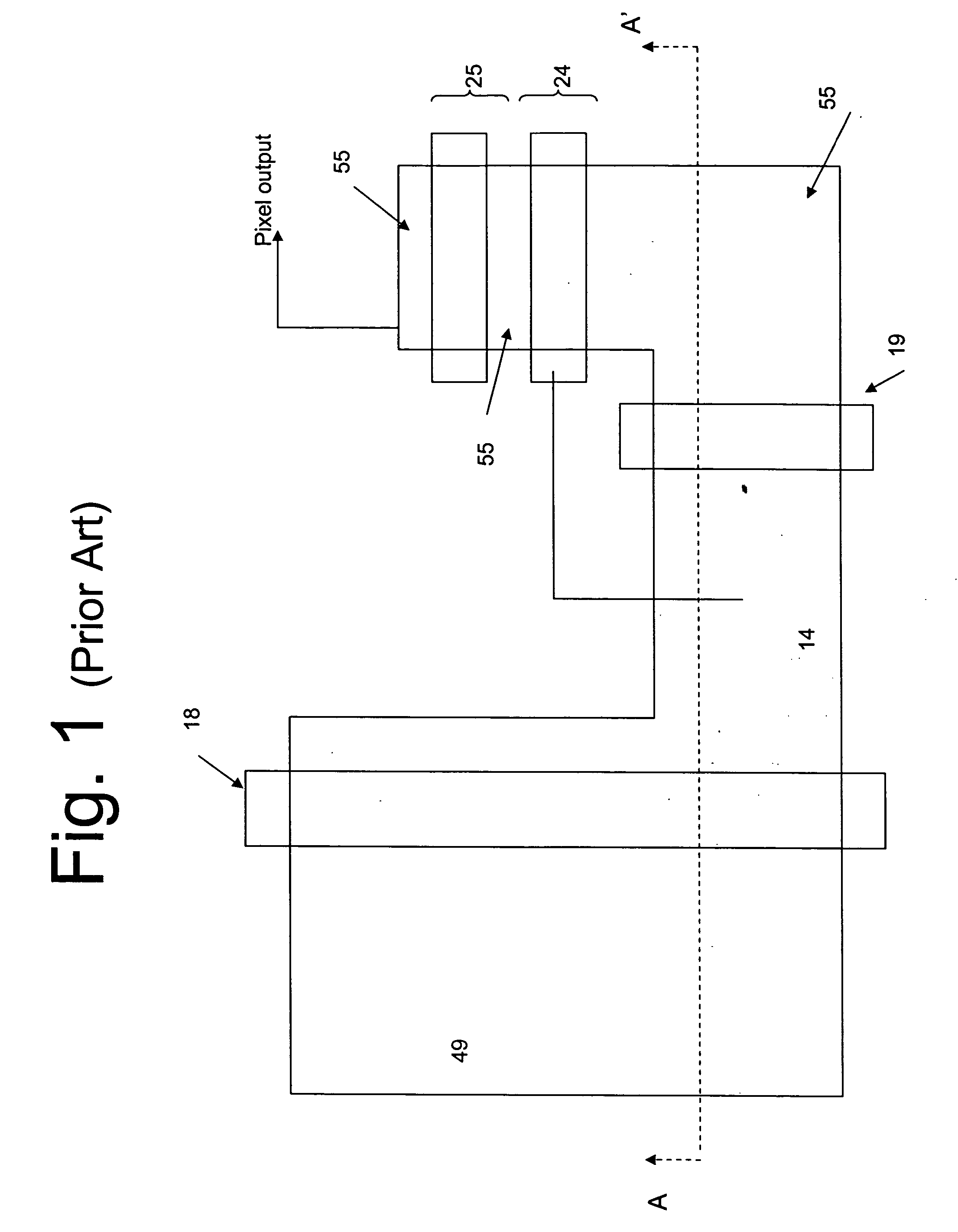
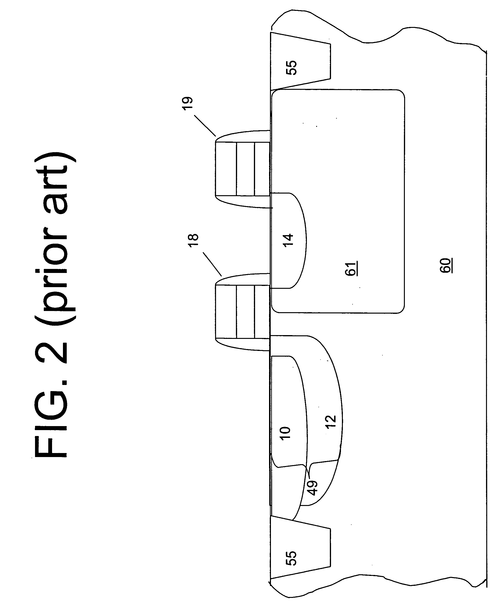
First, there can be a lag problem since the pixel uses a transfer transistor 18 for transferring charge to the floating diffusion region 14.
Next, charge leakage is another problem associated with the conventional p-n-p photodiode 49.
One source of such leakage occurs when the transfer transistor 18 gate length is too short, causing sub-threshold current to become significantly high due to charge breakdown between n-type regions on both sides of the transfer gate channel.
However, raised photodiodes, such as described in U.S. application Ser. No. 10 / 443,891, assigned to Micron Technology, Inc., and incorporated herein by reference, also have problems with leakage current across the elevated p-n junctions.

Method used


Image

  • Raised photodiode sensor to increase fill factor and quantum efficiency in scaled pixels
  • Raised photodiode sensor to increase fill factor and quantum efficiency in scaled pixels
  • Raised photodiode sensor to increase fill factor and quantum efficiency in scaled pixels

Examples


Embodiment Construction

[0023] In the following detailed description, reference is made to the accompanying drawings, which form a part hereof and show by way of illustration specific embodiments in which the invention may be practiced. These embodiments are described in sufficient detail to enable those skilled in the art to practice the invention, and it is to be understood that other embodiments may be utilized, and that structural, logical, and electrical changes may be made without departing from the spirit and scope of the present invention. The progression of processing steps described is exemplary of embodiments of the invention; however, the sequence of steps is not limited to that set forth herein and may be changed as is known in the art, with the exception of steps necessarily occurring in a certain order.

[0024] The terms “wafer” and “substrate,” as used herein, are to be understood as including silicon, silicon-on-insulator (SOI) or silicon-on-sapphire (SOS) technology, doped and undoped semi...


PUM


Abstract

An image pixel cell with a doped, hydrogenated amorphous silicon photosensor, raised above the surface of a substrate is provided. Methods of forming the raised photosensor are also disclosed. Raising the photosensor increases the fill factor and the quantum efficiency of the pixel cell. Utilizing hydrogenated amorphous silicon decreases the leakage and barrier problems of conventional photosensors, thereby increasing the quantum efficiency of the pixel cell. Moreover, the doping of the photodiode with inert implants like fluorine or deuterium further decreases leakage of charge carriers and mitigates undesirable hysteresis effects.

Description

FIELD OF THE INVENTION [0001] The present invention relates generally to digital image sensors and methods of fabrication thereof and in particular to photosensors used in a pixel sensor cell. BACKGROUND OF THE INVENTION [0002] Typically, a digital imager array includes a focal plane array of pixel cells, each one of the cells including a photosensor, e.g. a photogate, photoconductor, or a photodiode. In a CMOS imager a readout circuit is connected to each pixel cell which typically includes a source follower output transistor. The photosensor converts photons to electrons which are typically transferred to a floating diffusion region connected to the gate of the source follower output transistor. A charge transfer device (e.g., transistor) can be included for transferring charge from the photosensor to the floating diffusion region. In addition, such imager cells typically have a transistor for resetting the floating diffusion region to a predetermined charge level prior to charge ...

Claims


Application Information

Patent Timeline
IPC IPC(8): H01L27/146H01L31/062
CPCH01L27/14603H01L27/14609H01L27/14632H01L27/14692H01L27/14687H01L27/14689H01L27/14643
Inventor MOULI, CHANDRA
Owner MICRON TECH INC
Learn More