
Induction machine rotors with improved frequency response

a technology of frequency response and induction machine, which is applied in the direction of dynamo-electric machines, asynchronous induction motors, electrical apparatus, etc., can solve the problems of large electrical power consumption for conversion of electrical energy to useful work, significant difficulties in reliable grid operation and connected equipment, and high frequency response of rotors. achieve the effect of reducing the requirement for grid maintenance, reducing the magnetizing current in the rotor, and improving the power factor of the transfer of power

Inactive Publication Date: 2005-12-08
DUFF WILLIAM B JR
View PDF4 Cites 13 Cited by
  • Summary
  • Abstract
  • Description
  • Claims
  • Application Information

AI Technical Summary

Benefits of technology

[0072] The present invention generally relates to the use of electrical charge storage devices in the rotors of induction machines. Optimal induction machine rotor electrical field requirements increase with rotational velocity and inversely to frequency. Pseudocapacitance and other inverse frequency capacitance adjustment methods are employed to provide for that need and thereby improve induction machine rotor performance parameters. Optimization of electrical reactance is the foundation for improvements in power transfer, torque, efficiency, stability, thermodynamics, vibration, thermodynamics and bearing life in rotational induction machines. LC rotor methods and designs are outlined herein to achieve these objectives.
[0132] 48) reduce the severity and duration of light flicker due to motor starting;

Problems solved by technology

Conversion of electrical energy to useful work consumes a great quantity of electrical power.
The frequency response of rotors has heretofore posed a great challenge and difficulty.
The presence of significant levels of subharmonic and harmonic frequencies and especially resonances at these frequencies can pose significant difficulties to reliable operation of the grid and connected equipment.
The benefits of these capacitors often tend to decrease with distance from the load.
The exact circuit behavior, of real electrical components, is of course somewhat more complex than these mathematical modeling approximations.
Of course resistance, losses and work serve to damp these forces in realizable devices.
Therefore an AC induction motor cannot produce any torque when it is spinning at synchronous speed.
Similarly, an induction generator cannot produce any electrical power when it is spinning at synchronous velocity.
However, as stated AC induction motor / generators are functionally useless at this speed.
This low power factor requires a large source of magnetizing VARs to start the motor.
There are well known undesirable effects associated with the use of these capacitor banks.
Also when motor flywheel behavior is present, a circuit disconnect upstream from a shunt capacitor bank may produce a destructive transient overvoltage condition.
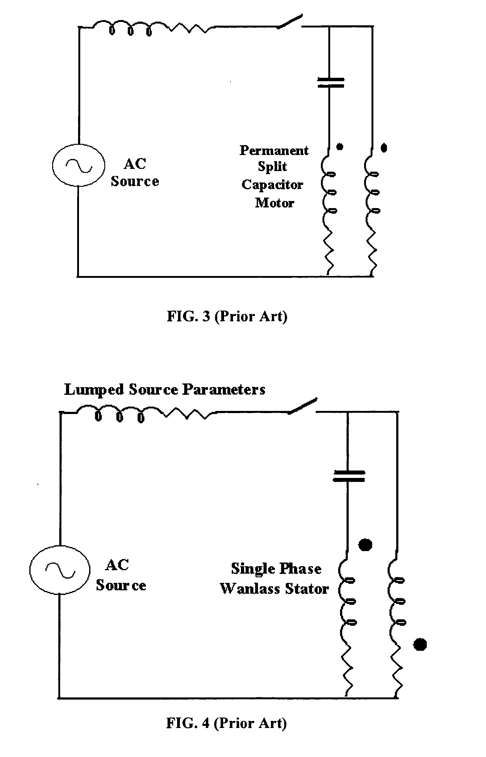
One fundamental disadvantage of existing single phase and three phase motors is frequency or bandwidth related.
There is a significant challenge in optimizing the power factor, efficiency and thus VA efficiency of inductive machines over a wide range of loads.
This challenge is further complicated by generation mode operation and alternate motor / generator service.
Finally, the use of adjustable frequency power electronic devices with induction machines to form variable frequency or adjustable frequency drives (ASD) further increases the challenge.
The voltage however has spikes or momentary high magnitudes.
The high voltage spikes create bearing problems in induction motors.
This accelerates motor end of life.
It is well known that the limitations to induction motor capabilities are generally ferromagnetic related rather than conductor related.
This is at the expense of electrical efficiency, however, unless a slip energy recovery circuit is used.
Since wound rotor motors require brush maintenance, initial cost and upkeep are typically higher than for squirrel cage motors.
In adjustable speed drives, as frequency is increased, the effects of leakage inductance tend to become more significant.
Thus the maximum available torque tends to decrease rapidly with increased frequency.

Method used


Image

  • Induction machine rotors with improved frequency response
  • Induction machine rotors with improved frequency response
  • Induction machine rotors with improved frequency response

Examples


Embodiment Construction

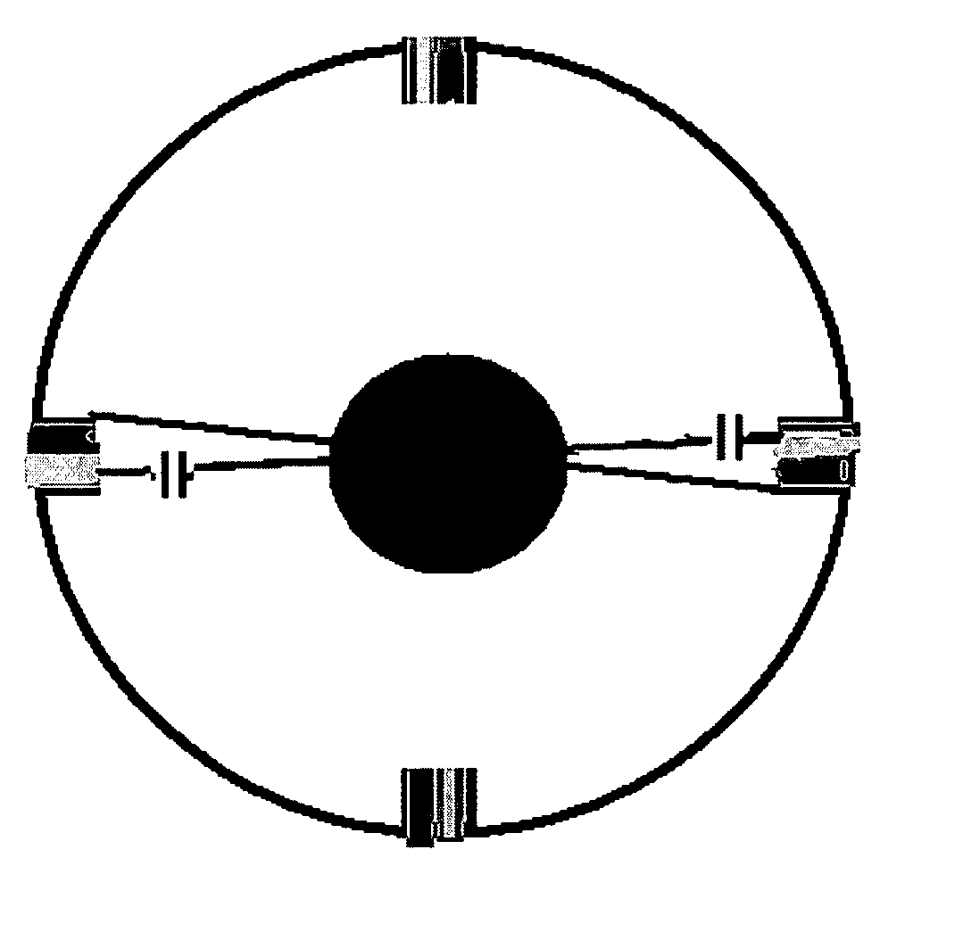
[0169] The rotor core and winds form an inductive circuit element. One or more capacitors can be added to the rotor to generally increase the power factor and thereby increase the power transfer and power conversion characteristics of the device. It is well known that capacitors and inductors can be combined in various LC configurations. These configurations can include series, shunt and hybrid combinations of the circuit elements.

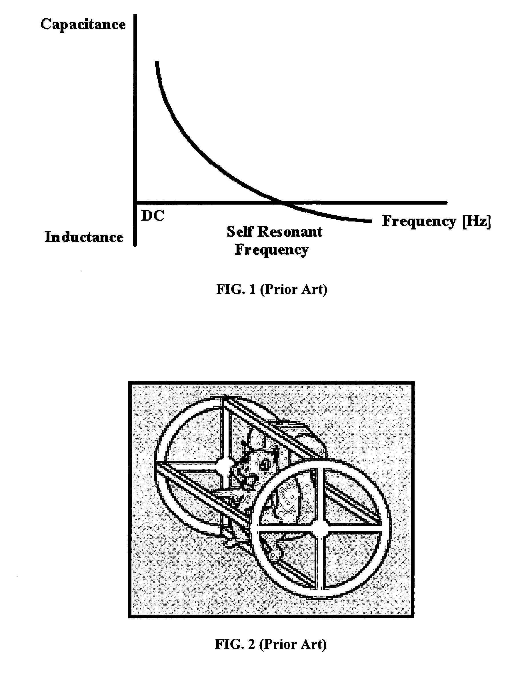
[0170] At the moment of engagement of an induction motor, the rotor is generally motionless. At this instant the stator and rotor are electromagnetically coupled to their greatest extent. Significant magnetizing VARs are required by induction motors at the moment of engagement. As the rotor within the induction machine accelerates, the electrical frequency in the rotor decreases. To maintain a resonant or quasiresonant electrical circuit in the rotor as the rotor electrical frequency is changed, a variation of capacitance is required.

[0171] A simple LC r...


PUM


Abstract

The present invention generally relates to the use of electrical charge storage devices in the rotors of induction machines. Optimal induction machine rotor electrical field requirements increase with rotational velocity and inversely to frequency. Pseudocapacitance and other inverse frequency capacitance adjustment methods are employed to provide for that need and thereby improve induction machine rotor performance parameters. Optimization of electrical reactance is the foundation for improvements in power transfer, torque, efficiency, stability, thermodynamics, vibration, thermodynamics and bearing life in rotational induction machines. LC rotor methods and designs are outlined herein to achieve these objectives.

Description

CROSS-REFERENCE TO RELATED APPLICATIONS [0001] This application claims priority to U.S. Provisional Patent Application Ser. No. 60 / 571,975 entitled “INDUCTION MACHINE ROTORS WITH IMPROVED FREQUENCY RESPONSE”, filed May 18, 2004, which is hereby incorporated herein by reference.TECHNICAL FIELD [0002] The present invention generally relates to the use of electrical charge storage devices in rotors. In particular, the present invention relates to electrical charge storage devices, such as capacitors, in induction machine rotors for improved frequency response BACKGROUND OF THE INVENTION [0003] Conversion of electrical energy to useful work consumes a great quantity of electrical power. There are therefore significant advantages to improving the operational parameters of their energy conversion mechanisms. The rotor is the ultimate point of electrical load in electromagnetic energy conversion to useful rotational work. The frequency response of rotors has heretofore posed a great challe...

Claims


Application Information

Patent Timeline
IPC IPC(8): H02K17/18H02K17/30
CPCH02K17/30H02K17/185H02K17/18H02K17/08
Inventor DUFF, WILLIAM B. JR.
Owner DUFF WILLIAM B JR
Learn More