Test arrangement including anisotropic conductive film for testing power module

a technology of anisotropic conductive film and power module, which is applied in the direction of electrical testing, measurement devices, instruments, etc., can solve the problems of power supply voltage transient, inaccurate power loss measurement, and no value to the user, so as to improve the voltage stability of the module, reduce the impedance connection, and reduce the stray inductance

Active Publication Date: 2005-12-08
INFINEON TECH AMERICAS CORP
View PDF4 Cites 2 Cited by
  • Summary
  • Abstract
  • Description
  • Claims
  • Application Information

AI Technical Summary

Benefits of technology

[0017] With these features, the size (height) of the sheet interconnections is significantly less than that of the known pogo-pins and allows for an interconnection with little stray inductance. The improved voltage stability within the module due to this reduced impedance connection allows the large decoupling capacitors to be removed from the module.
[0018] Further, the fine grid of conductors in the film sheet increases the number of contact points to each pad on the module. The short length of these conductors minimizes their resistance. Thus the total interconnection resistance (contact resistance and conductor resistance) is reduced. During high-current power-loss testing, the conductors in the sheet will dissipate far less power. This power dissipation is not enough to cause any significant change in the total interconnection resistance, resulting in a stable power-loss operating point.

Problems solved by technology

These have no value to the user and are only used for power loss testing.
The known pogo pin arrangement can generate both stray inductance and interconnection resistance (contact resistance plus conductor resistance) which can cause oscillation and power loss at the power supply input and output, causing power loss measurements to be inaccurate.
Also, if the pogo pins make poor or intermittent contact with the corresponding test points on the module, voltage transients can occur when power is applied.
Such transients may waste testing time, since the test cannot be completed until the transients settle down, and they may even damage the semiconductor module.
Any increase in the separation between the supply and the module supply pins will increase stray inductance in the supply circuit.
This stray inductance in turn will result in voltage oscillations (dynamic variations) on the supply pins of the module which will change the power loss and can even cause failure of the module, due to transient over-voltage conditions.
This total interconnection resistance between the test socket and the module, although reasonably small, can be significant, especially at high-current power-loss testing.
The voltage-drop across the interconnections also increases as the current flowing through them causes heating, thereby increasing the interconnection resistance further and changing the power-loss operating point (that is, more of the input power is dissipated within the interconnections, reducing the input power to the module).

Method used


Image

  • Test arrangement including anisotropic conductive film for testing power module
  • Test arrangement including anisotropic conductive film for testing power module
  • Test arrangement including anisotropic conductive film for testing power module

Examples


Embodiment Construction

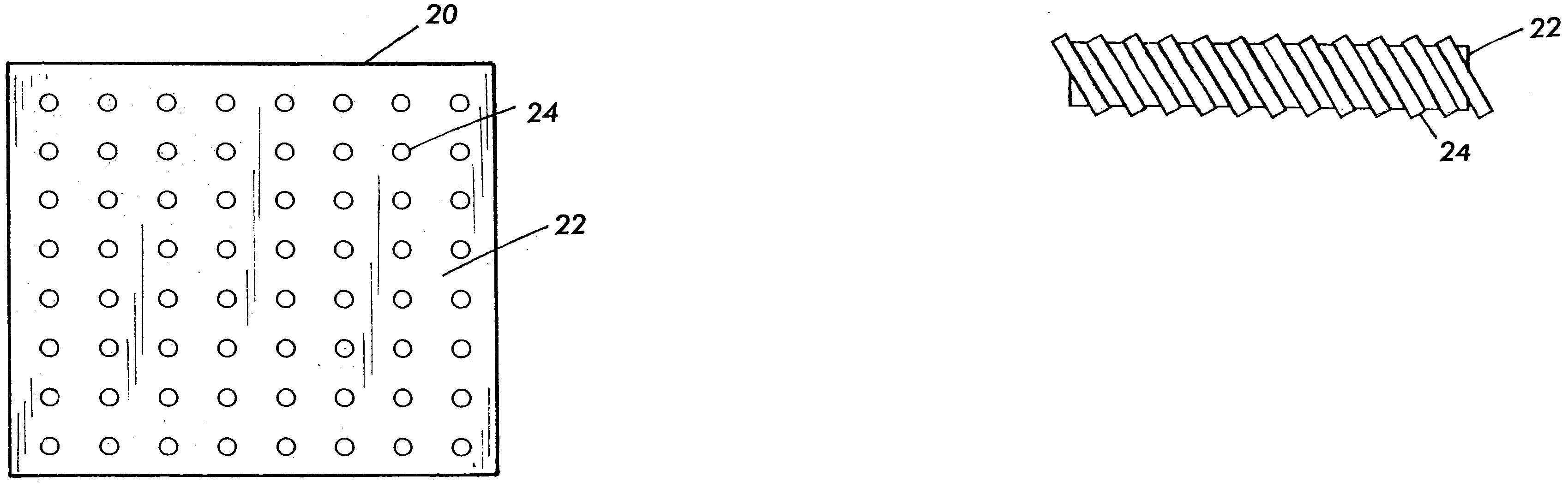
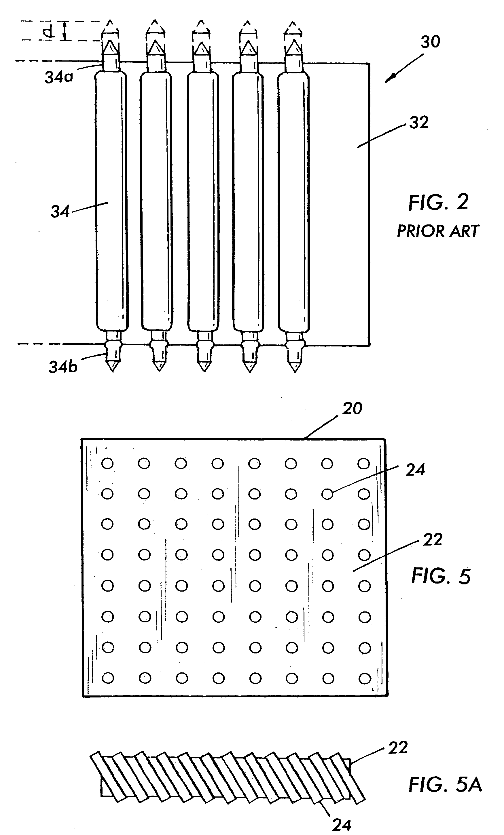
[0026] As seen in FIG. 4, the module under test (not shown) is held in a holding block 55 which is lowered onto the test board by a vertical shaft 57. Disposed in the test socket is an anisotropic conductive elastomeric sheet 20, shown in plan view in FIG. 5, i.e., an elastomeric sheet that conducts substantially in only one direction.

[0027] One example of such a sheet is shown in FIG. 5A. In this example, the sheet 20 comprises an elastomeric matrix 22, and a large number of conductors 24 extending substantially in parallel through the matrix 22. As seen, because of the flexibility of the matrix, the matrix can compress to an extent when the module is pressed down by the holding block, which may cause the conductors to tilt while still remaining parallel, providing more reliable communication between the test board and the module under test, than with the prior pogo-pin arrays.

[0028] The sheet may take other structures besides that shown in FIG. 5A, as long as it provides conduct...


PUM


Abstract

A testing apparatus and method for testing a semiconductor device, and more particularly a test arrangement for measuring a guaranteed power loss of a semiconductor module, not requiring the module to have on-board decoupling capacitors for the power loss test. The conventional pogo-pin array and test socket are replaced by a novel low cost anisotropic conductive elastomer and a low cost socket, the conductive polymer providing electrical communication between the socket and the module under test.

Description

CROSS-REFERENCE TO RELATED APPLICATION [0001] The present application is based upon and claims priority of provisional application No. 60 / 576,727, filed Jun. 3, 2004, incorporated by reference.BACKGROUND OF THE INVENTION [0002] 1. Field of the Invention [0003] This invention relates to a testing apparatus and method for testing a semiconductor device, and more particularly to a test setup for measuring a guaranteed power loss of a semiconductor module, in which the module is not required to have on-board capacitors for the power loss test. [0004] 2. Background Art [0005] Currently, to perform power loss testing on a semiconductor module, two large capacitors must be included in the package. These have no value to the user and are only used for power loss testing. Integrated power supply manufacturers cannot guarantee a power loss on their data sheets unless they use complex test processes and on-board capacitors. FIG. 3 shows a board to be tested in which internal input capacitors “...

Claims


Application Information

Patent Timeline
Patent Type & Authority Applications(United States)
IPC IPC(8): G01R1/073G01R31/26
CPCG01R1/0735
Inventor SCHAFFER, CHRISTOPHER P.STRYDOM, JOHANCIUFFOLI, ANDREA
Owner INFINEON TECH AMERICAS CORP
Why Eureka
Try Eureka