Control circuit of display device, display device and electronic appliance having the same, and driving method of the same

a control circuit and display device technology, applied in static indicating devices, cathode-ray tube indicators, instruments, etc., can solve the problems of inefficient utilization of inability to efficiently use physical area of memory, so as to reduce the number of mounting pins, reduce the production cost of control circuit, and reduce the effect of production cost of display devi

Inactive Publication Date: 2005-12-08
SEMICON ENERGY LAB CO LTD
View PDF17 Cites 14 Cited by
  • Summary
  • Abstract
  • Description
  • Claims
  • Application Information

AI Technical Summary

Benefits of technology

[0027] Accordingly, downsizing and reduction in production cost of the control circuit can be achieved, thereby downsizing and reduction in production cost of the display device can be achieved. The display device incorporating the control circuit of the invention can be driven with an area gray scale method or a time gray scale method to perform gray scale display. In addition, a light emitting element typified by an EL (Electro Luminescence) element includes a pair of electrodes and a layer containing a light emitting material provided therebetween. The light emitting element generates one or both of light emitted in returning from an excited singlet state to a ground state (fluorescence) and light emitted in returning from an excited triplet state to a ground state (phosphorescence).
[0028] As set forth above, according to the control circuit of a display device of the invention, a single main video data storage means

Problems solved by technology

However, the aforementioned conventional configuration involves a time margin for the period after the termination of the read-out operation for one address until the start of the next data read-out operation, since data reading from the video memory is required to be performed in synchronous with the half-cycle of S_CK, which results in inefficient utilization

Method used


Image

  • Control circuit of display device, display device and electronic appliance having the same, and driving method of the same
  • Control circuit of display device, display device and electronic appliance having the same, and driving method of the same
  • Control circuit of display device, display device and electronic appliance having the same, and driving method of the same

Examples


embodiment mode 1

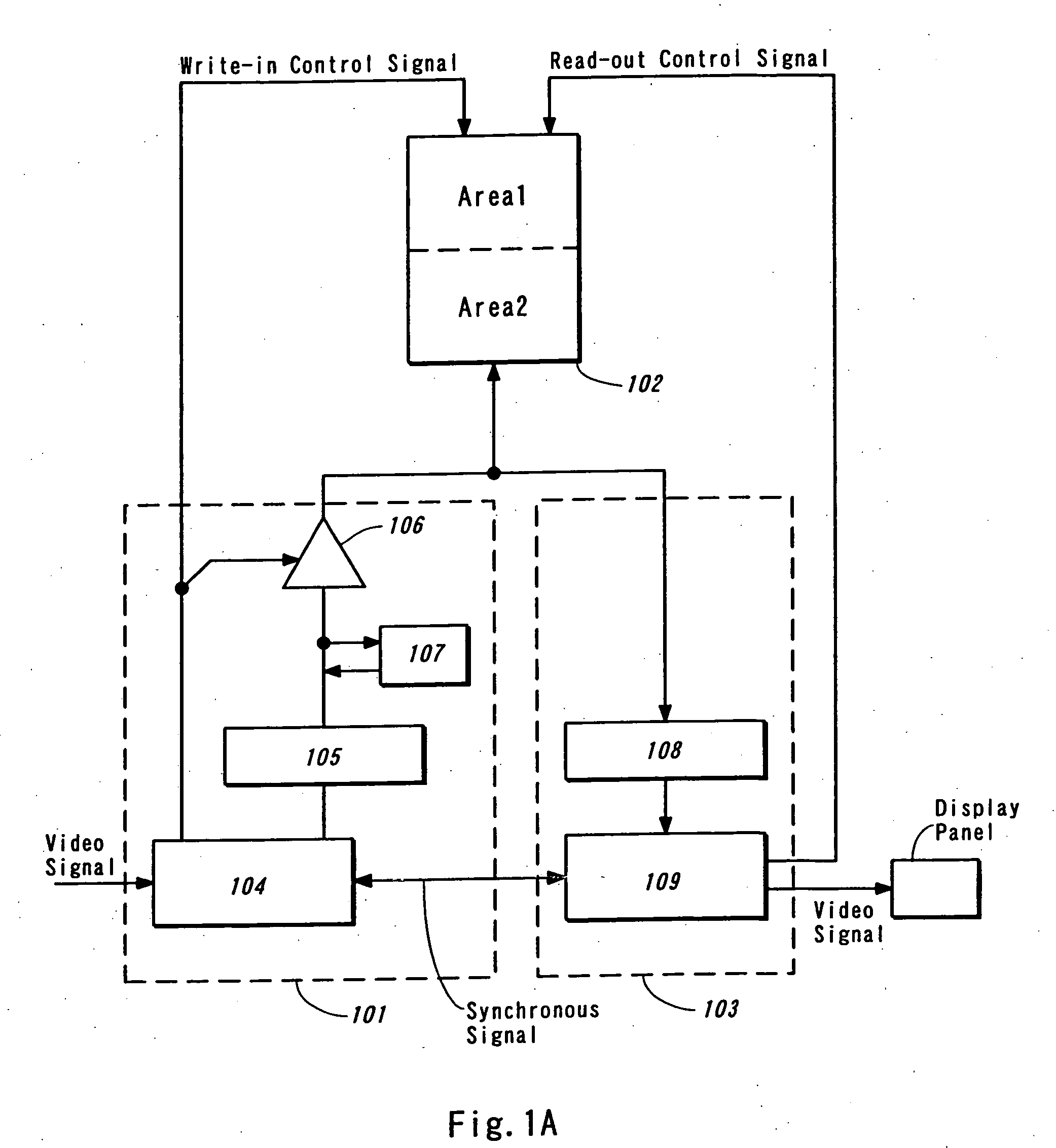
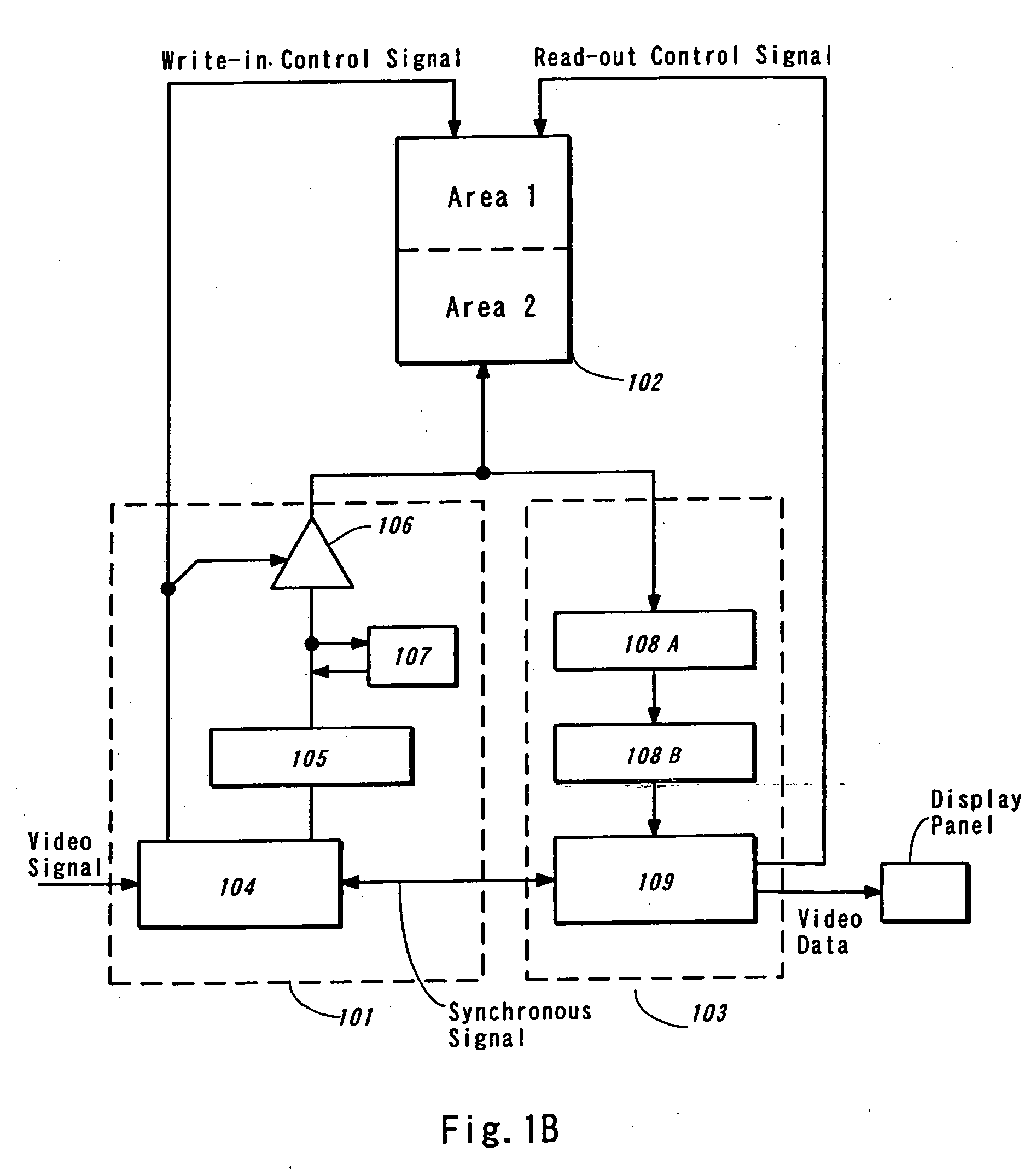
[0047]FIG. 1A schematically illustrates an exemplary configuration of a control circuit of a display device of the invention. The control circuit comprises a video data write-in circuit 101 including a video data format converting unit 104 and a write-in video data storage unit 105, a main video data storage unit 102, and a video data read-out circuit 103 including a read-out video data storage unit 108 and a display control unit 109. Upon receiving a video signal, the video data format converting unit 104 converts the video signal in format, for example to the video data appropriate for a time gray scale display in pixels of a display panel if the display device is driven with the time gray scale method, and then writes the video data having the converted format to the write-in video data storage unit 105. The write-in video data storage unit 105 holds a predetermined quantity of video data appropriate for being written to the main video data storage unit 102 for a fixed period, an...

embodiment mode 2

[0066]FIG. 7 is a schematic diagram illustrating an exemplary configuration of a control circuit of a display device of the invention, which is different from Embodiment Mode 1, and FIG. 8 illustrates the operation timing of the control circuit in Embodiment Mode 2 at read-out and write-in operations. This embodiment mode is similar to Embodiment Mode 1 in that the read-out operation is performed in asynchronous with a half-cycle of S_CK. However, in this embodiment, the read-out operation is performed not in predetermined clock cycles as a base period as in Embodiment Mode 1 in which the read-out operation is performed continuously, but the read-out operation is performed in the display cycle of one row in the display panel as a base period. Specifically, video data for one row that has an appropriate quantity for the display timing of the display panel is read out from the main video data storage unit within the base period, and then held in the read-out video data storage unit. M...

embodiment 1

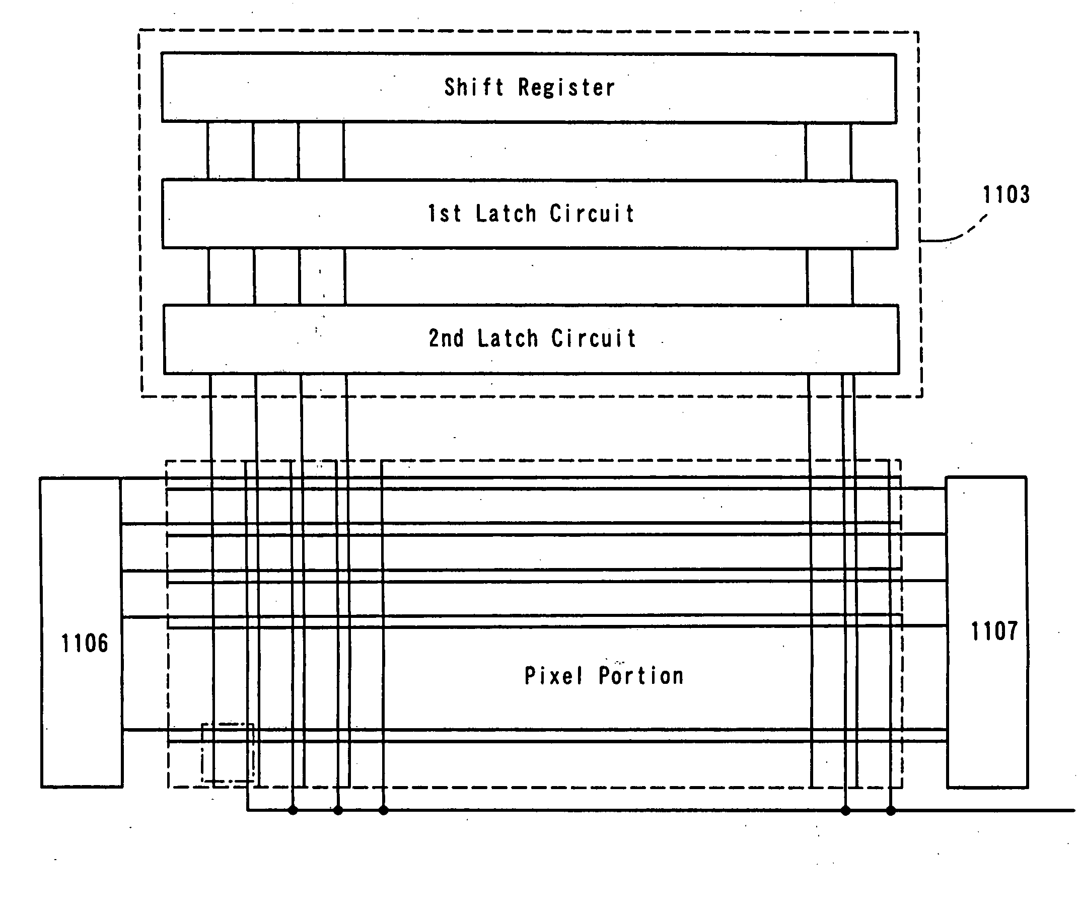
[0074] In this embodiment, description is made on an exemplary display device using the invention with reference to FIGS. 11A and 11B. A display device shown in FIG. 11A mainly comprises a control circuit 1101 having one video data memory for storing video data, and a display panel 1102 having pixels each of which includes a light emitting element such as an EL element. The control circuit 1101 may be, for example, the control circuit shown in FIGS. 1A, 1B or 7, which are described in Embodiment Modes 1 and 2. The display panel 102 includes a source driver 1103 connected to a source signal line, a gate driver 1104 connected to a gate signal line and a pixel portion 1105. The pixel portion includes pixels arranged in matrix. Each of the source driver 1103 and the gate driver 1104 may be a known driver circuit.

[0075] Although only a single gate driver is employed in this configuration, two gate drivers may be employed as shown in FIG. 11B where a write-in gate driver 1106 and an eras...


PUM


Abstract

Downsizing and improvement in operating efficiency of a control circuit of a display device is achieved. Two video data storage units that have conventionally been used in a control circuit are combined into one, and an address area thereof is divided in half. One of the areas is used as a writing area while the other is used as a reading area, and these areas are alternately switched at regular intervals, for example per frame period. Video data reading from the video data storage unit is performed not in synchronous with a half-cycle of a source clock. Instead, a predetermined quantity of video data is read out continuously in a plurality of consecutive clock cycles, and the video data is temporarily held in a read-out video data storage unit and the like so as to be transmitted to a display panel at any time desired. Write-in operation is performed in the period in which the read-out operation is not performed until a write-in video data storage unit is completely rewritten.

Description

BACKGROUND OF THE INVENTION [0001] 1. Field of the Invention [0002] The present invention relates to a display device, and more particularly to a display device comprising a display panel having pixels each of which includes a light emitting element, and a control circuit having a storage means for storing video data. [0003] Control circuit of a display device means a circuit for converting a video signal received in format to the video data enabling a gray scale display in pixels of a display panel, writing the video data to a storage means, and then outputting the video data read out from the storage means to the display panel. [0004] 2. Description of the Related Art [0005] There is known a display device comprising a display panel having pixels each of which includes a light emitting element, and a peripheral circuit for inputting signals to the display panel, in which images are displayed by controlling the emission of the light emitting elements. [0006] In such a display panel...

Claims


Application Information

Patent Timeline
IPC IPC(8): G09G3/20G09G3/36G09G3/30G09G3/32G09G5/00G09G5/393G09G5/395G09G5/399
CPCG09G3/2096G09G3/3275G09G5/393G09G2360/18G09G5/399G09G2300/0842G09G2310/0251G09G5/395G09G3/30G09G3/20
Inventor OZAKI, TADAFUMI
Owner SEMICON ENERGY LAB CO LTD
Why Eureka
Try Eureka