
Electrophoretic particle, process for its production, and its use

a technology of electrophoretic particle and process, applied in the field of electrophoretic particle, can solve the problems of deterioration in display quality, difficulty in ensuring uniform display quality, and conventional electrophoretic display devices have not yet had sufficiently satisfactory display properties, and achieve excellent display properties, high zeta potential, and high dispersibility in a dispersing medium.

Active Publication Date: 2005-12-08
E INK CORPORATION
View PDF18 Cites 56 Cited by
  • Summary
  • Abstract
  • Description
  • Claims
  • Application Information

AI Technical Summary

Benefits of technology

[0010] Under these circumstances, it is an object of the present invention to provide an electrophoretic particle, which can give electrophoretic display devices having extremely excellent display properties such as display responsiveness and contrast, a process for its production, and its use thereof, more particularly, a microcapsule and sheet for electrophoretic display, as well as an electrophoretic display device and an electronic equipment.
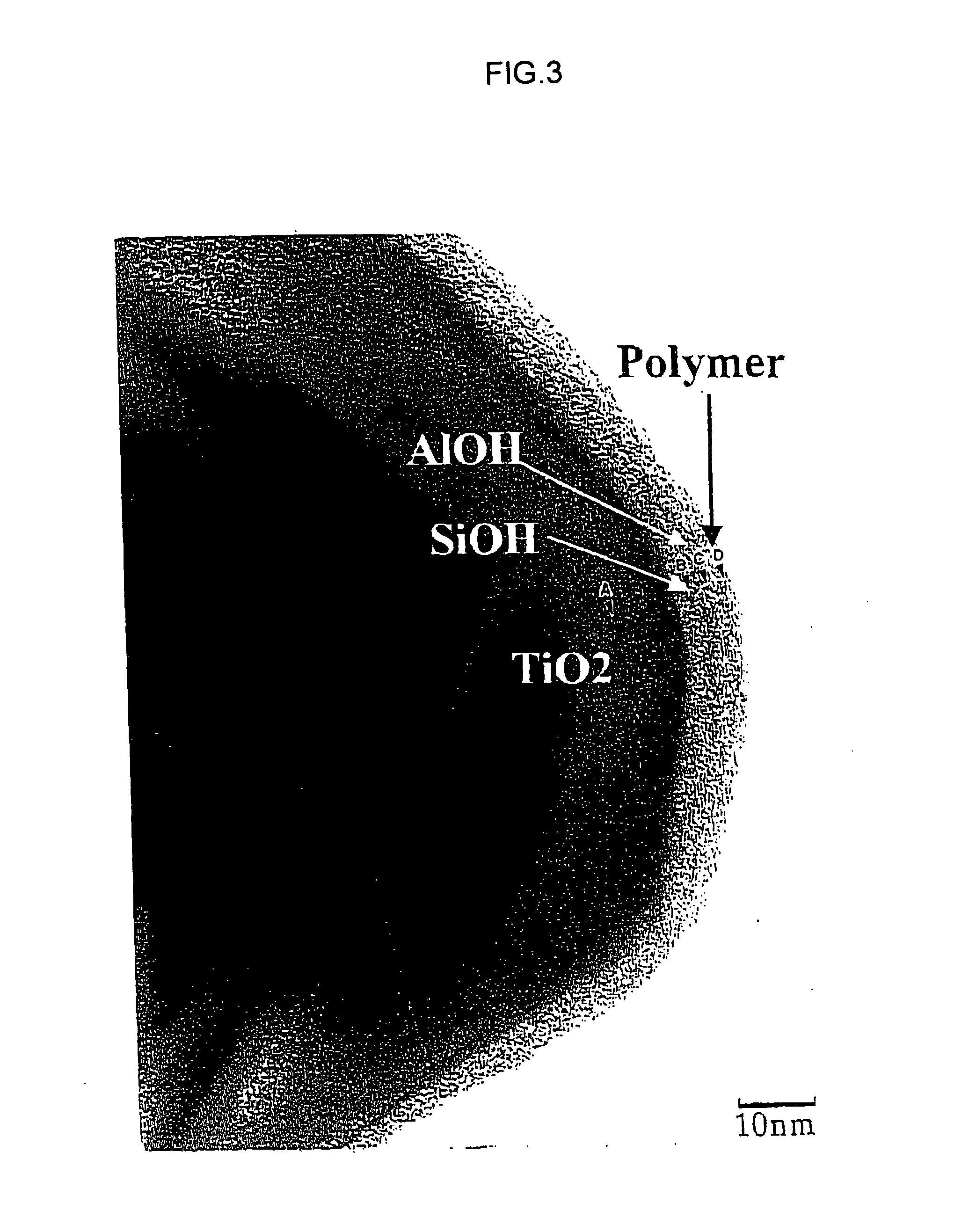
[0011] In order to attain the above object, the present inventors have intensively studied and, as a result, they have found that regarding an electrophoretic particle comprising a pigment particle and a polymer layer formed on a surface of the pigment particle, when an average particle diameter of the pigment particle, an average thickness of the polymer layer, and a coating ratio of the polymer layer to an entire surface of the pigment particle are adjusted in their prescribed ranges, an electrophoretic display device having extremely excellent display properties such as display responsiveness and contrast can be obtained, and that for producing an electrophoretic particle using a dispersion polymerization method, when procedures and conditions are appropriately selected, the above electrophoretic particle can be obtained extremely effectively, thereby completing the present invention.
[0019] The electrophoretic particle of the present invention provides a dispersing system having a high zeta potential and has extremely high dispersibility in a dispersing medium. Therefore, the electrophoretic particle of the present invention, as well as the microcapsule and sheet for electrophoretic display according to the present invention using the same, make it possible to obtain an electrophoretic display device and an electronic equipment having extremely excellent display properties such as display responsiveness and contrast. In addition, the process for producing an electrophoretic particle according to the present invention makes it possible that, in the production of an electrophoretic particle having a polymer layer on a surface of a pigment particle, sufficiently high levels can be attained in both of a polymerization rate of all monomer components and a polymerization rate of a polymer corresponding to the polymer layer coating the surface of the pigment particle.

Problems solved by technology

The cell-type electrophoretic display device, however, has a serious problem that electrophoretic particles may unevenly be distributed to cause a deterioration in display quality.
This method, however, has a serious problem that it may be quite difficult to evenly inject a dispersion into a great number of voids and, in the case of a dispersion using a volatile dispersing medium, the properties of the dispersion may be changed during injection work, it may be difficult to ensure uniform display quality.
However, the conventional electrophoretic display devices have not yet had sufficiently satisfactory display properties when compared with the required level of performance both at the present time and in the future, and for application to various display devices as described above, in particular, it has been necessary to further improve display properties such as display responsiveness and contrast.

Method used


Image

  • Electrophoretic particle, process for its production, and its use
  • Electrophoretic particle, process for its production, and its use
  • Electrophoretic particle, process for its production, and its use

Examples


example 1

[0188]

[0189] A separable four-neck flask with a volume of 400 mL, equipped with a stirring wing, was charged with 30 g of titanium oxide particles (trade name: TIPAQUE CR-90, available from Ishihara Sangyo Kaisha, Ltd.; average particle diameter, 0.25 μm; specific surface area, 13 m2 / g) as pigment particles, 93 g of ethanol, 23 g of water, 1 g of 25 wt % aqueous ammonia, 0.3 g of γ-methacryloxypropyltolymethoxysilane (trade name: KBM-503, available from Shin-Etsu Chemical Co., Ltd.) as a coupling agent having a polymerizable reactive group, and 0.8 g of a 38 wt % methanol solution of octadecyldimethyl[3-(tolymethoxysilyl)propyl]ammonium chloride (trade name: LS-6985, available from Shin-Etsu Chemical Co., Ltd.). This flask was placed in an ultrasound bath (trade name: BRANSON5210, available from Yamato Scientific Co., Ltd.), in which ultrasound dispersing treatment was carried out for 2 hours while stirring.

[0190] After the dispersing treatment, the flask was removed from the bath....

example 2

[0198]

[0199] The same flask as used in Example 1 was charged with 30 g of titanium oxide particles (trade name: TIPAQUE CR-90, available from Ishihara Sangyo Kaisha, Ltd.; average particle diameter, 0.25 μm; specific surface area, 13 m2 / g) as pigment particles, 93 g of ethanol, 23 g of water, 1 g of 25 wt % aqueous ammonia, 0.6 g of γ-methacryloxypropyltolymethoxysilane (trade name: KBM-503, available from Shin-Etsu Chemical Co., Ltd.) as a coupling agent having a polymerizable reactive group, and 2.4 g of a 38 wt % methanol solution of octadecyldimethyl[3-(trimethoxysilyl)propyl]ammonium chloride (trade name: LS-6985, available from Shin-Etsu Chemical Co., Ltd.). This flask was placed in 50° C. ultrasound bath (trade name: BRANSON5210, available from Yamato Scientific Co, Ltd.), in which ultrasound dispersing treatment was carried out for 2 hours while stirring.

[0200] After the dispersing treatment, the flask was removed from the bath. While the content of the flask was stirred un...

example 3

[0205]

[0206] The same flask as used in Example 1 was charged with 30 g of titanium oxide particles (trade name: TIPAQUECR-90, available from Ishihara Sangyo Kaisha Ltd.; average particle diameter, 0.25 μm; specific surface area, 13m2 / g) as pigment particles, 108 g of isopropyl alcohol, 8 g of water, 4 g of a 25 wt % aqueous ammonia, and 1.2 g of γ-methacryloxypropyltrimethoxysilane (trade name: KBM-503, available from Shin-Etsu Chemical Co., Ltd.) as a coupling agent having a polymerizable reactive group. This flask was placed into a 50° C. ultrasound bath (trade name: BRANSON5210, available from Yamato Scientific Co., Ltd.), in which ultrasound dispersing treatment was carried out for 2 hours while stirring.

[0207] After the dispersing treatment, the flask was removed from the bath. While the content of the flask was stirred under a nitrogen atmosphere, there was added a mixture of 1.2 g of methacryloyloxyethyltrimethylammonium chloride and 4.8 g of lauryl methacrylate as monomer c...


PUM

PropertyMeasurementUnit
Lengthaaaaaaaaaa
Fractionaaaaaaaaaa
Fractionaaaaaaaaaa

Abstract

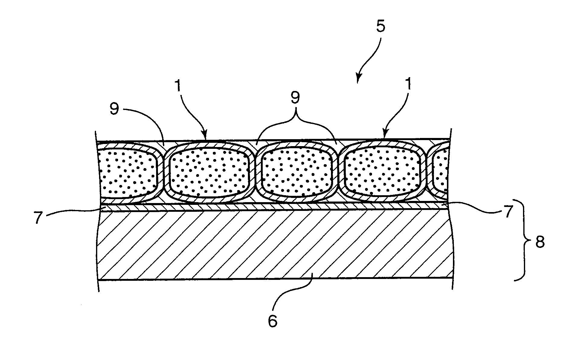
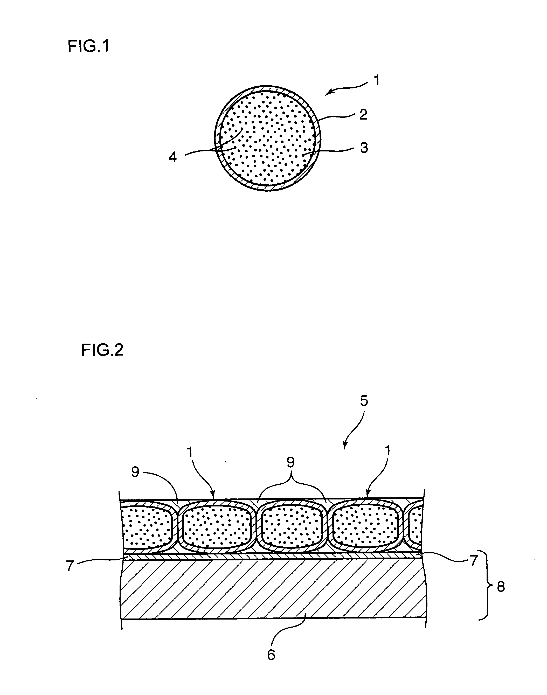
An electrophoretic particle including: a pigment particle having an average particle diameter of 1 μm or smaller; and a polymer layer having an average thickness of 1 to 500 nm formed on a surface of the pigment particle, wherein 50% or higher of an entire surface of the pigment particle is coated with the polymer layer. The electrophoretic particle can be produced by radical polymerization using a polymerization initiator in a state where a pigment particle and monomer components are present in a solvent. The electrophoretic particle can be used in a microcapsule and a sheet for electrophoretic display, as well as an electrophoretic display device and an electronic equipment.

Description

BACKGROUND OF THE INVETION [0001] 1. Field of the Invention [0002] The present invention relates to an electrophoretic particle, a process for its production, and its use. [0003] 2. Description of the Related Art [0004] There is a phenomenon called electrophoresis, in which charged particles dispersed in a liquid migrate in the liquid in response to an external electric field, and much attention has been paid to display devices making use of this phenomenon, referred to as “electrophoretic display devices.” The electrophoretic display devices fall under the category of the non-light emitting display devices, and have many excellent properties such as extremely lower power consumption, a higher level of visibility (wider viewing angle), and capability of recording displayed contents for a long term without consuming electricity, when compared with liquid crystal displays. [0005] For example, Japanese Patent Publication No. 50-15115 discloses a cell-type electrophoretic display device...

Claims


Application Information

Patent Timeline
IPC IPC(8): B01J13/14G02B26/00G02F1/167G09G3/34
CPCB01J13/14G02F1/167G02F2001/1678Y10T428/2991Y10T428/2984
Inventor MIYAZAKI, ATSUSHINISHIDA, TOSHIFUMIKUSHINO, MITSUOKIKUTA, TERUO
Owner E INK CORPORATION
Learn More