Method and system for accurately calculating latency variation on an end-to-end path in a network

Inactive Publication Date: 2005-12-08
MICROSOFT TECH LICENSING LLC
View PDF11 Cites 41 Cited by
  • Summary
  • Abstract
  • Description
  • Claims
  • Application Information

AI Technical Summary

Benefits of technology

[0010] Briefly, the present invention provides a method and system including a high-resolution, per-packet measurement tool that operates by sending a predetermined number of packets from a sender machine to a receiver machine with measurement information inserted into the packet. The sending machine associates a sequence number and the sender's local time (to a precision of 100 ns) with each packet, such as by stamping the information into the data section of each packet via a timestamp component running in the s

Problems solved by technology

Each interface can send and receive network traffic at a finite rate, and if the rate at which traffic is directed to a network interface exceeds the rate at which the network interface can forward the traffic onward, congestion occurs.
As a result, applications sending network data experience varying latency or traffic loss.
For example, certain applications can tolerate some degree of traffic loss, while others cannot.
Because network resources are finite, there are parts of the network wherein resources are unable to meet demand.
Indeed, although general attempts have been made to attempt to measure how QoS actually helps transmission of data over a network, existing tools are inadequate for quantifying the benefit of QoS.
For example, one such tool reports results at a very coarse level, by sending an amount of data and determining how long it took to receive that data.
As a result, relatively little information is obtained with this technique, and indeed, other factors such as non-network related delays are factored into the transmission time.
RTT helps transport level protocols in estimating the congestion in the network, but because the congestion

Method used


Image

  • Method and system for accurately calculating latency variation on an end-to-end path in a network
  • Method and system for accurately calculating latency variation on an end-to-end path in a network
  • Method and system for accurately calculating latency variation on an end-to-end path in a network

Examples


Example

Exemplary Operating Environment

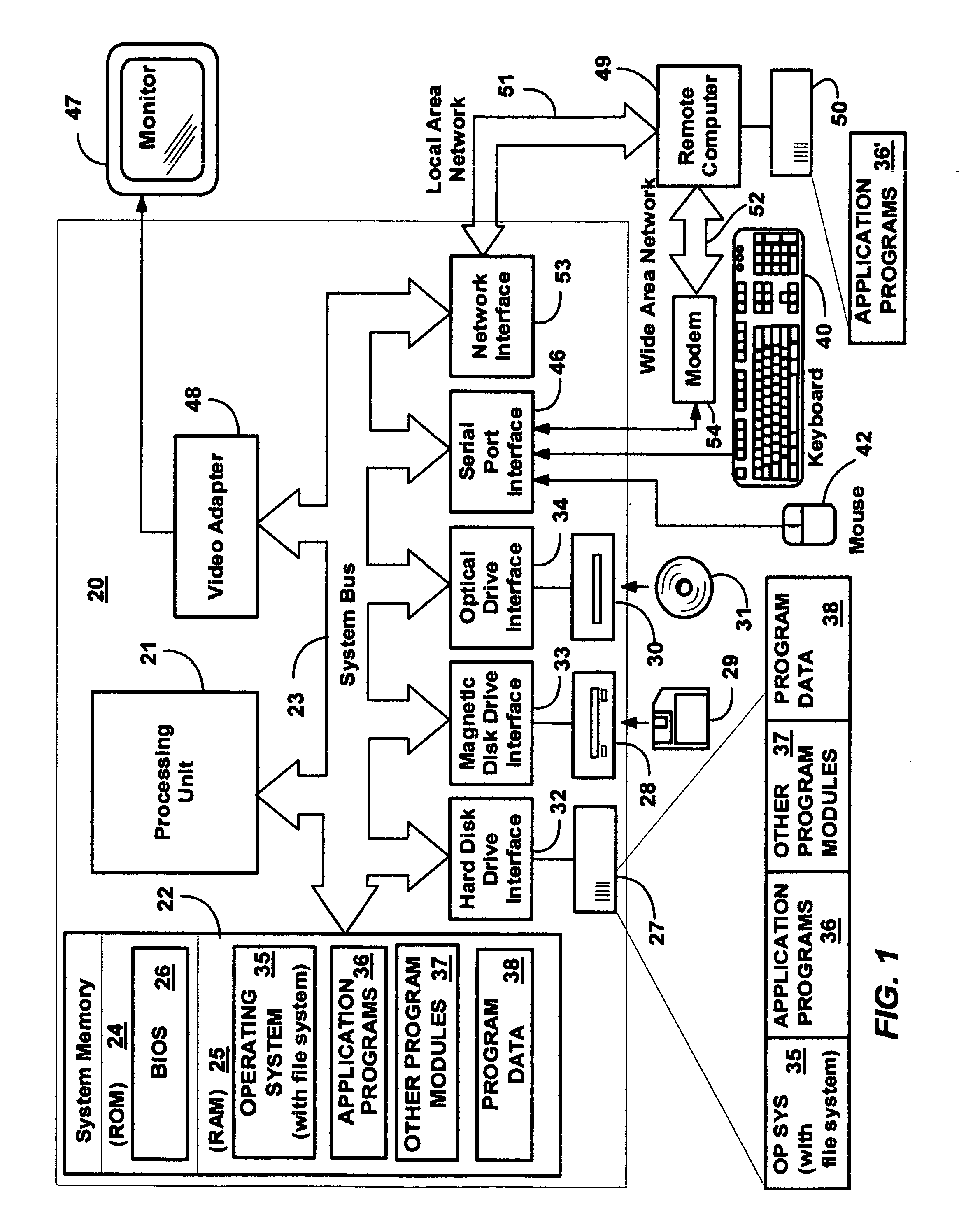
[0028]FIG. 1 and the following discussion are intended to provide a brief general description of a suitable computing environment in which the invention may be implemented. Although not required, the invention will be described in the general context of computer-executable instructions, such as program modules, being executed by a personal computer. Generally, program modules include routines, programs, objects, components, data structures and the like that perform particular tasks or implement particular abstract data types.

[0029] Moreover, those skilled in the art will appreciate that the invention may be practiced with other computer system configurations, including hand-held devices, multi-processor systems, microprocessor-based or programmable consumer electronics, network PCs, minicomputers, mainframe computers and the like. The invention may also be practiced in distributed computing environments where tasks are performed by remote processing...


PUM


Abstract

A high-resolution, per-packet measurement tool for analyzing a computer network that operates by sending a predetermined number of packets from a sender machine to a receiver machine with measurement information inserted into the packet. The system kernel at the sending machine stamps a sequence number and the sender's local time into the data section of each packet. When packets arrive at the receiver machine, they are similarly stamped by the receiving machine's kernel with the receiving machine's local time. The maintained packet information serves as the basis for latency analysis. For example, one set of latencies can be obtained with QoS mechanisms turned on, and another set with QoS mechanisms turned off, whereby the benefits of the QoS mechanisms can be accurately determined. To analyze the latencies, the present invention normalizes each time and each latency into relative latency information. Clock skew and timer jumps may be handled as part of the normalization.

Description

FIELD OF THE INVENTION [0001] The present invention relates generally to computer networks, and more particularly to an analysis tool for measuring latencies in a computer network. BACKGROUND OF THE INVENTION [0002] Networks interconnect hosts using a variety of network devices, including host network adapters, routers, switches and hubs, each of which include network interfaces for interconnecting the various devices via cables and fibers. Applications send data over a network by submitting it to an operating system, after which it becomes network traffic. Network devices generally use a combination of hardware and software to forward network traffic from one network interface to another. Each interface can send and receive network traffic at a finite rate, and if the rate at which traffic is directed to a network interface exceeds the rate at which the network interface can forward the traffic onward, congestion occurs. Network devices may handle this condition by queuing traffic ...

Claims


Application Information

Patent Timeline
IPC IPC(8): H04J3/06H04L12/28
CPCH04L12/2854
Inventor MADHAVAPEDDI, SHREEDHARBERNET, YORAMSUNDARAM, RAJESHHOLMES, JOHN
Owner MICROSOFT TECH LICENSING LLC
Why Eureka
Try Eureka