
Highly-integrated low-mass solar sail

a solar sail and high-integration technology, applied in the field of spacecraft propulsion systems, can solve the problems of reducing mass, reducing the structural integrity of the sail, and not being available in layers, so as to prevent the propagation of rips in the material, reduce the amount of mass, and facilitate further mass reduction.

Inactive Publication Date: 2005-12-15
ANVIK CORP
View PDF4 Cites 7 Cited by
  • Summary
  • Abstract
  • Description
  • Claims
  • Application Information

AI Technical Summary

Benefits of technology

[0016] Another advantage of the invention is that its laser ablation process allows the manufacturer flexibility in the ablation pattern in order to suit user-specific needs.
[0017] Another advantage of the invention is that the pattern ablated into the material's surface may be selected in order to prevent the propagation of rips in the material.
[0018] Another advantage of the invention is that it allows further mass reduction by miniaturizing and integrating electronic components that otherwise might need to be included in the payload, possibly requiring additional wiring and mounting components.
[0019] Another advantage of the invention is that it enables increased functionality through the integration of electronic components such as photovoltaic cells and sensors on the surface of the sail.
[0020] The invention has been described in its preferred utility as a solar sail, but other objects, features, and advantages of the invention will be apparent from the following written description, claims, abstract, and the annexed drawings.

Problems solved by technology

This freely available energy makes solar sails an attractive propulsion system, but the relatively small momentum carried by photons presents a technical challenge to reduce mass.
While an intermediate step might be simply to reduce the thickness of the underlying substrate, we must note that although polyester is readily available in 0.5 μm thickness, it is not an ideal sail material because it is easily degraded by the sun's ultraviolet radiation, potentially leading to a loss of the structural integrity of the sail; and while polyimide can withstand ultraviolet radiation, it is not available in layers much thinner than 8 μm.
However, given that it is rigid, it cannot be packaged in a very small volume like polyester and polyimide, and therefore, solar sails fabricated from the material would likely need to be assembled in space, adding significantly to the complexity of building and deploying the sail.
Thus, no currently available material fulfills this role cost-effectively.

Method used


Image

  • Highly-integrated low-mass solar sail
  • Highly-integrated low-mass solar sail
  • Highly-integrated low-mass solar sail

Examples


Embodiment Construction

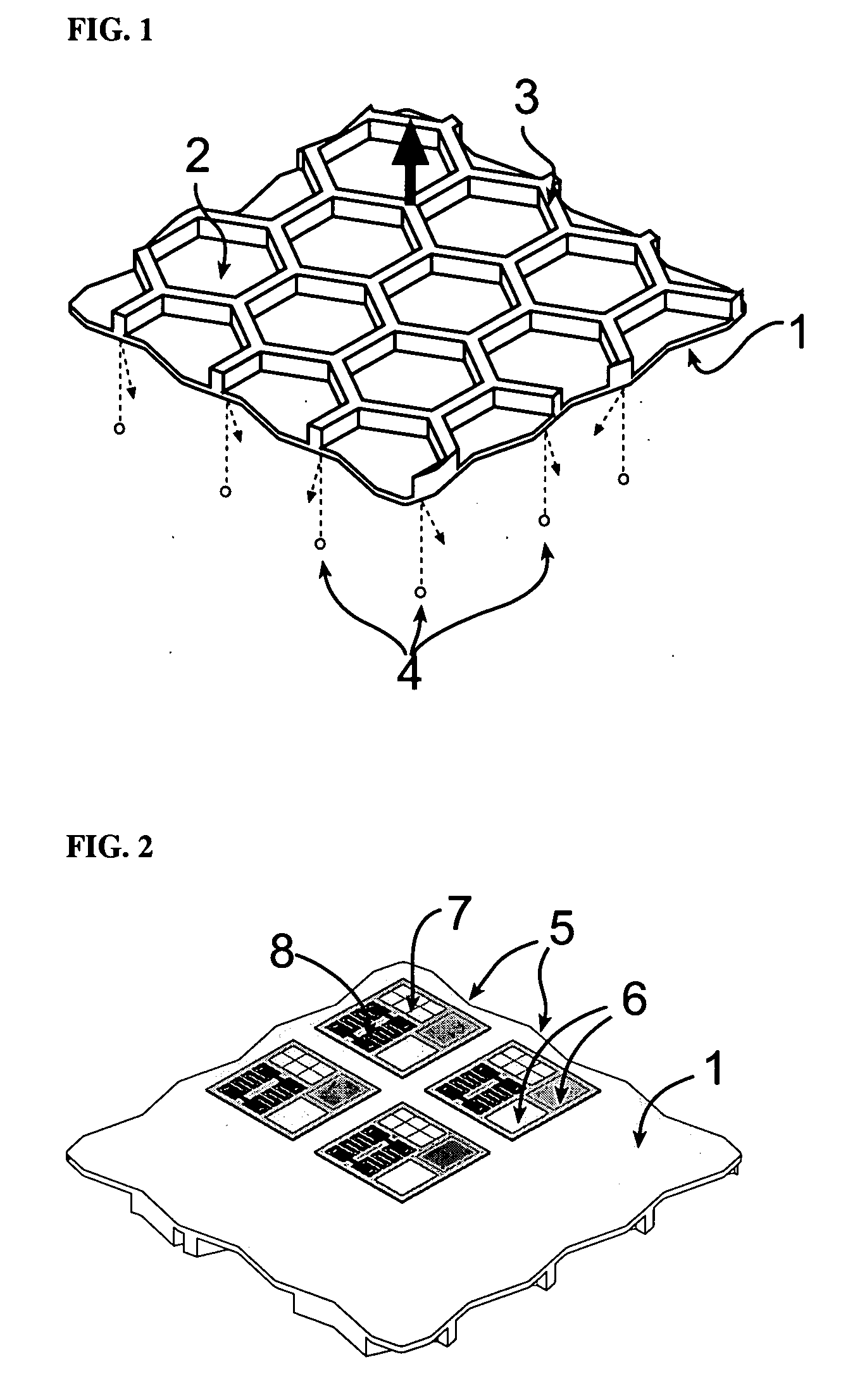
[0029]FIG. 1 is a perspective illustration of the solar sail material in its preferred embodiment. The material consists of a substrate layer such as polyimide, coated with a reflective material on its first surface 1, and textured by photoablation on the second surface to leave a tessellated pattern on the second surface. This pattern may be selected by the producer of the material to suit the specific application of the material. The pattern shown in FIG. 1 is a hexagonal grid consisting of flat-bottomed wells denoted by 2 and ridges denoted by 3. A hexagonal grid is suggested here for its relative structural strength and for its tendency not to propagate rips in the material. The reflective coating on the first surface 1 reflects inbound photons 4 emitted by the sun, collecting and imparting their momentum to the sail and thus to the payload.

[0030]FIG. 2 is a perspective illustration of the microelectronic integration capability of the invention. Since the first surface 1 remain...


PUM


Abstract

Low mass-per-unit-area plastic film, preferably polyimide, prepared by a process of controlled treating of a supply of plastic film, possibly with one surface reflectively coated, at a microlithography workstation with included photoablation optics. This treatment achieves significant controlled removal of material in a selected pattern by providing relative motion between untreated plastic film and the workstation's photoablation optics while controlling photoablation of a pattern in the film. The material has a significant quantity of the mass of its plastic removed by photoablation, leaving a tessellated pattern of ridges surrounding individual wells. The resulting low-mass, rip-resistant film retains the general attributes of a large-area plastic film. The treated film also retains its reflective surface, on which amorphous silicon may be deposited. The silicon may be thereafter crystallized, utilizing the same optics, and used for fabrication of microelectronics.

Description

CROSS-REFERENCE TO RELATED APPLICATION [0001] Not applicable. STATEMENT REGARDING FEDERALLY SPONSORED RESEARCH OR DEVELOPMENT [0002] Not applicable. BACKGROUND OF THE INVENTION [0003] 1. Field of the Invention [0004] This invention relates generally to spacecraft propulsion systems, and more specifically, to photolithography, photoablation, and crystallization techniques as part of a method for large-scale fabrication of highly-reflective reduced-mass-per-area solar sail with integrated microelectronics, MEMS, sensors, etc. [0005] 2. Description of Related Art [0006] The solar sail is a propulsive device that uses a thin reflecting foil to deflect sunlight, transferring photon momentum to the sail and thereby accelerating it and the attached payload. Although the pressure per unit area of solar photons is rather small, it can be utilized to accelerate spacecraft to very high velocities-spacecraft with very low mass that are driven by very large sails can take advantage of the steady...

Claims


Application Information

Patent Timeline
IPC IPC(8): B64G1/40
CPCB64G1/407Y10T428/24479
Inventor KLOSNER, MARK A.JAIN, KANTI
Owner ANVIK CORP
Learn More