Magnetic recording medium, method of producing magnetic recording medium and magnetic storage apparatus

Inactive Publication Date: 2005-12-15
FUJITSU LTD
View PDF11 Cites 18 Cited by
  • Summary
  • Abstract
  • Description
  • Claims
  • Application Information

AI Technical Summary

Benefits of technology

100] crystal orientation of the crystal grains are inclined towards one of two sides partitioned by a plane that is formed by the recording direction and a substrate normal which is normal to the substrate surface. According

Problems solved by technology

In the case where the disk surface has the increased surface roughness, it is difficult to improve the electromagnetic conversion characteristics of the magnetic disk by reducing the distance between a magnetic head and the disk surface, and there is a limit to increasing the recording density according to this approach.
According to such deposition or sputtering, most of the depositing or sputtering grains will not reach the su

Method used


Image

  • Magnetic recording medium, method of producing magnetic recording medium and magnetic storage apparatus
  • Magnetic recording medium, method of producing magnetic recording medium and magnetic storage apparatus
  • Magnetic recording medium, method of producing magnetic recording medium and magnetic storage apparatus

Examples


first embodiment sample emb-1

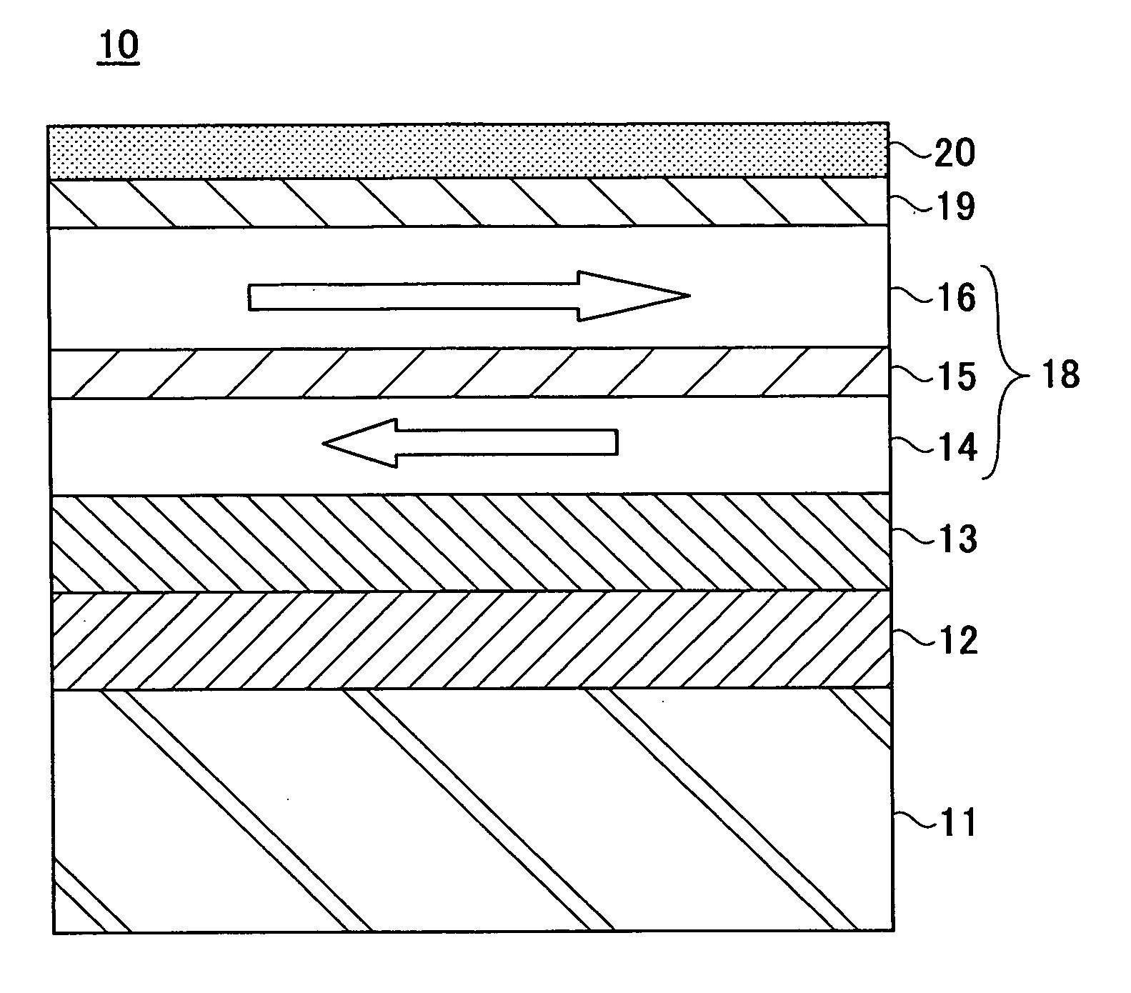
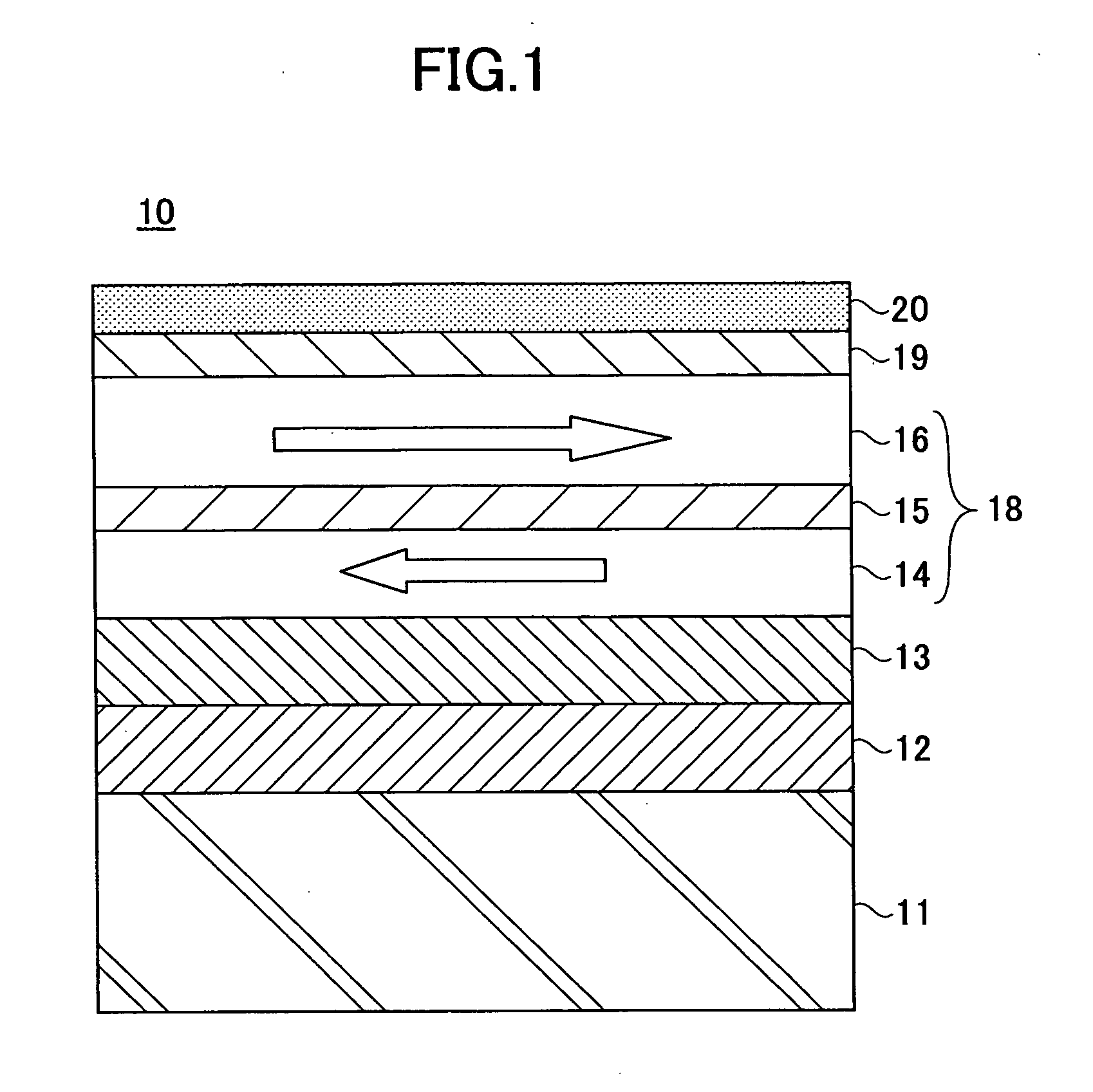
[0079] The D.C. magnetron sputtering apparatus 30 was used to form a magnetic disk having the following structure, as the magnetic recording medium 10.

[0080] The magnetic disk created includes a glass substrate 11 having a diameter of 65 mm, an AlRu seed layer 12 having a thickness of 10 nm, a Cr underlayer 13 having a thickness of 4.5 nm, a Co90Cr10 first magnetic layer 14 having a thickness of 2 nm, a Ru nonmagnetic spacer layer 15 having a thickness of 0.7 nm, a CoCrPt12B7Cu4 second magnetic layer 16 having a thickness of 15 nm, and a C protection layer 19 having a thickness of 4.5 nm.

[0081] The glass substrate 11 was heated to 180° C. within vacuum by the PBN heater prior to forming the AlRu seed layer 12. The glass substrate 11 was heated similarly to 230° C. prior to forming the Ru nonmagnetic spacer layer 15. Using the sputtering apparatus 30 shown in FIGS. 5 and 6, the erosion region 31a was formed in the AlRu sputtering target 31 between a position where the radius is 67....

second embodiment sample emb-2

[0082] Using the sputtering apparatus 30 shown in FIGS. 5 and 6, the erosion region 31a was formed in the AlRu sputtering target 31 between a position where the radius is 47.0 mm and a position where the radius is 77.0 mm from the disk center of the glass substrate 11. A center position of the erosion region 31a is located at a radius of 62.0 mm from the disk center of the glass substrate 11. The incident angle θINC of the sputtering particles from the outer peripheral side of the glass substrate 11 was set to a center incident angle of 38.7 degrees (of a range from 23.0 degrees to 49.6 degrees) at the outer (or outermost) peripheral position DOUT shown in FIG. 6, and to a center incident angle of 51.3 degrees (of a range from 41.2 degrees to 58.4 degrees) at the inner (or innermost) peripheral position DIN shown in FIG. 6. Otherwise, the second embodiment sample Emb-2 was created under the same conditions as the first embodiment sample Emb-1 described above.

third embodiment sample emb-3

[0083] Using the sputtering apparatus 30 shown in FIGS. 5 and 6, the erosion region 31a was formed in the AlRu sputtering target 31 between a position where the radius is 47.0 mm and a position where the radius is 57.0 mm from the disk center of the glass substrate 11. A center position of the erosion region 31a is located at a radius of 52.0 mm from the disk center of the glass substrate 11. The incident angle θINC of the sputtering particles from the outer peripheral side of the glass substrate 11 was set to a center incident angle of 28.8 degrees (of a range from 23.0 degrees to 34.0 degrees) at the outer (or outermost) peripheral position DOUT shown in FIG. 6, and to a center incident angle of 45.0 degrees (of a range from 41.2 degrees to 48.4 degrees) at the inner (or innermost) peripheral position DIN shown in FIG. 6. Otherwise, the third embodiment sample Emb-3 was created under the same conditions as the first embodiment sample Emb-1 described above.


PUM


Abstract

A magnetic recording medium has a seed layer provided on a substrate surface, an underlayer provided on the underlayer, and a recording layer provided on the underlayer. Information is recorded in the recording layer by magnetizing the recording layer in a recording direction. The seed layer is formed by a polycrystal of crystal grains made of an alloy material having a B2 crystal structure, and a [100] crystal orientation of the crystal grains are inclined towards one of two sides partitioned by a plane that is formed by the recording direction and a substrate normal which is normal to the substrate surface.

Description

BACKGROUND OF THE INVENTION [0001] This application claims the benefit of a Japanese Patent Application No. 2004-175720 filed Jun. 14, 2004, in the Japanese Patent Office, the disclosure of which is hereby incorporated by reference. [0002] 1. Field of the Invention [0003] The present invention generally relates to magnetic recording media, methods of producing magnetic recording media and magnetic storage apparatus, and more particularly to a magnetic recording medium for use in longitudinal magnetic recording, a method of producing such a magnetic recording medium and a magnetic storage apparatus using such a magnetic storage apparatus. [0004] 2. Description of the Related Art [0005] Recently, storage capacities of magnetic storage apparatuses used in personal computers and dynamic image recording apparatuses for home use have increased considerably. For example, there are magnetic disk drives, mainly for dynamic image recording, which have a storage capacity exceeding 100 GB. It i...

Claims


Application Information

Patent Timeline
IPC IPC(8): G11B5/62G11B5/66G11B5/738G11B5/73G11B5/82G11B5/84
CPCG11B5/66G11B5/7315G11B5/8404G11B5/7325G11B5/732G11B5/7379G11B5/73921G11B5/737G11B5/62
Inventor SATO, KENJI
Owner FUJITSU LTD
Why Eureka
Try Eureka