Semiconductor device and ic card
a technology of semiconductor devices and ic cards, applied in the field of semiconductor devices, can solve problems such as malfunction due to characteristic degradation, device breakage, and change of signal processing circuit characteristics
- Summary
- Abstract
- Description
- Claims
- Application Information
AI Technical Summary
Benefits of technology
Problems solved by technology
Method used
Image
Examples
first embodiment
(First Embodiment)
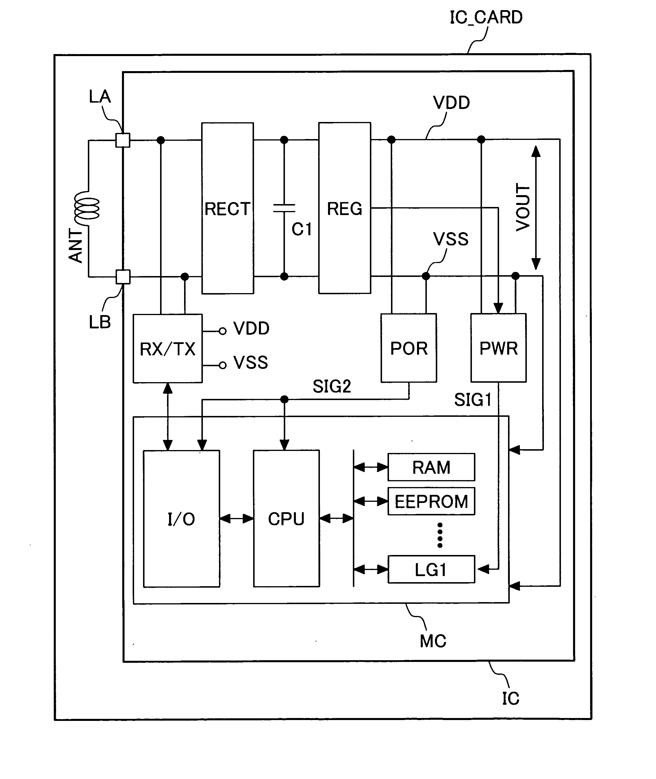
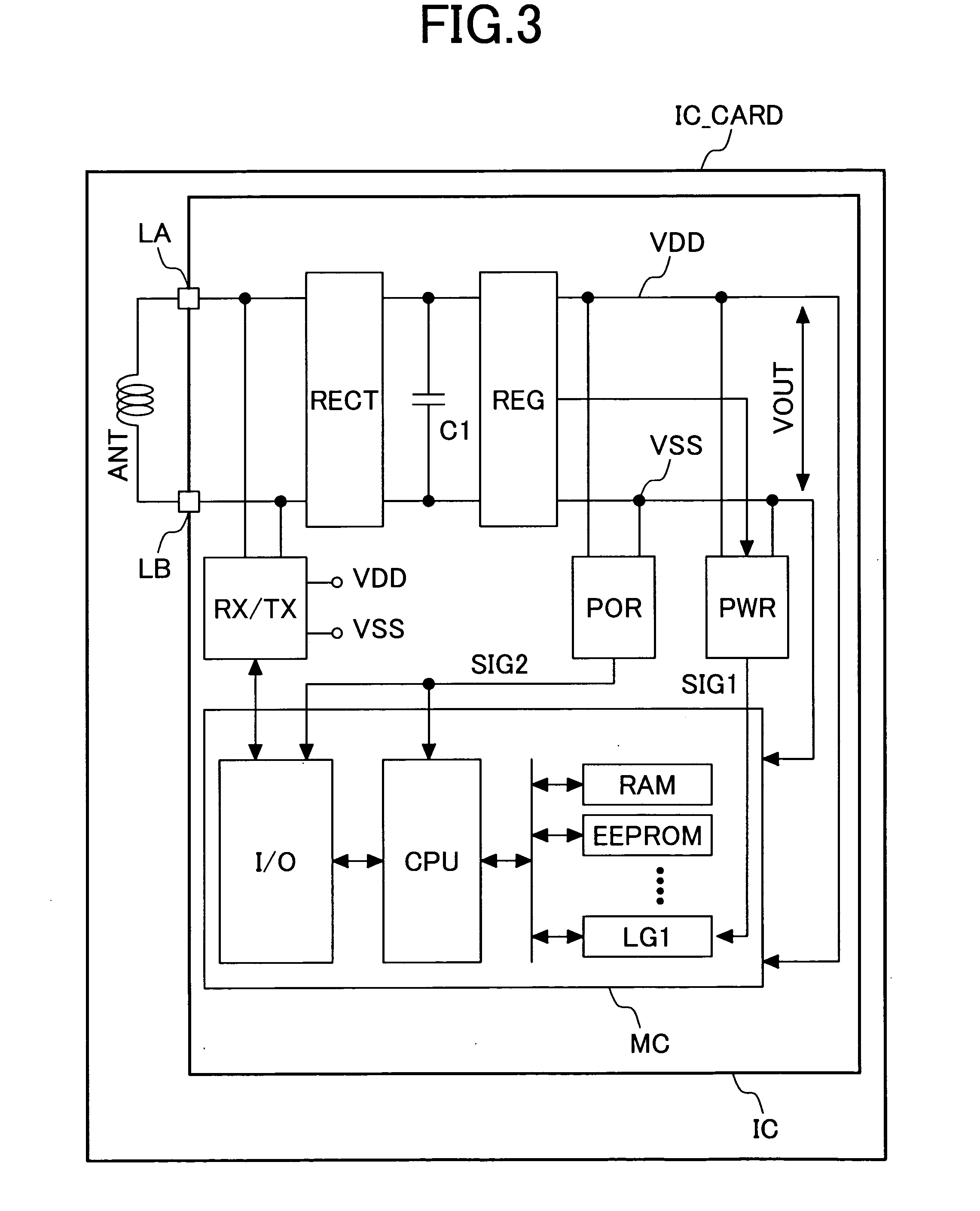
[0021]FIG. 3 is a block diagram of an embodiment of a semiconductor integrated circuit device provided with an operating current detector circuit according to the present invention and a contactless IC card having the semiconductor integrated circuit device mounted therein. The signal and power outputted in the form of electromagnetic wave from an interrogator (not shown) through an antenna are received by an antenna ANT incorporated in an IC card IC_CARD. Typically, the antenna ANT is an antenna coil formed of wound spiral of wire of a printed circuit board. The semiconductor integrated circuit IC is mounted on the printed circuit board having this antenna ANT formed thereon. This printed circuit board is molded with resin to form the IC card. Typically, the present invention is applied to a contactless IC card which does not have electrodes for I / O to and from outside on its surface. Of course, it is also possible to apply the present invention to a dual-type IC ...
second embodiment
(Second Embodiment)
[0041]FIG. 7 is a circuit diagram showing another embodiment of the voltage controlling circuit REG and the operating current detector circuit PWR in FIG. 4. The voltage comparator circuit VCC in FIG. 7 has the same configuration as that in FIG. 4. Meanwhile, the voltage controlling current source VCCS differs in that the drain of the NMOS M11 is directly connected to VDD.
[0042] The operating current detector circuit PWR in FIG. 7 is composed of the circuit described below. More specifically, the NMOS M12 whose gate terminal is connected to the output terminal of the operational amplifier circuit All is connected between the connection node N12 and the reference potential VSS. In this case, the size of the NMOS M12 is N times as large as that of the NMOS transistor M11. The reference current source IREF11 is connected between the power supply potential VDD and the connection node N12, the connection node 12 is connected to the input terminal of the inverter INV11...
third embodiment
(Third Embodiment)
[0047]FIG. 8 is a circuit diagram showing another embodiment of the operating current detector circuit PWR mounted in a semiconductor integrated circuit device according to the present invention. In this embodiment, a modification example of the operating current detector circuit PWR shown in FIG. 7 is described.
[0048] The operating current detector circuit PWR in FIG. 8 is composed of a circuit described below. That is, the NMOS M21 whose gate terminal is connected to the output terminal of the operational amplifier circuit A21 is connected between the connection node N21 and the reference potential VSS. The reference current source IREF 21 is connected between the power supply potential VDD and the connection node N21, an input terminal of the low pass filter LPF composed of the resistor R21 and the capacitor C11 is connected to the connection node N21, the PMOS M22 whose gate terminal is connected to the output terminal of the low pass filter LPF is connected b...
PUM
 Abstract
Description
Claims
Application Information
 - R&D
- Intellectual Property
- Life Sciences
- Materials
- Tech Scout
- Unparalleled Data Quality
- Higher Quality Content
- 60% Fewer Hallucinations
Browse by: Latest US Patents, China's latest patents, Technical Efficacy Thesaurus, Application Domain, Technology Topic, Popular Technical Reports.
© 2025 PatSnap. All rights reserved.Legal|Privacy policy|Modern Slavery Act Transparency Statement|Sitemap|About US| Contact US: help@patsnap.com


