Protected stent delivery system and packaging

a technology of stent and delivery system, which is applied in the direction of ear treatment, container, tray container, etc., can solve the problems of adverse effects of drugs, pericardial tissue of these jackets can degrade without protection, and are not suitable for medical devices which have jackets, coatings or components which are subject to oxygen or moisture degradation, etc., to reduce the level of sterilizing gas and facilitate the passage of sterilizing gas

Inactive Publication Date: 2005-12-15
DESIGN & PERFORMANCE CYPRUS
View PDF2 Cites 68 Cited by
  • Summary
  • Abstract
  • Description
  • Claims
  • Application Information

AI Technical Summary

Benefits of technology

[0022] The interior of the covered tray may be evacuated to aspirate sterilizing gas surrounding the pouch or covered tray to facilitate the passage of sterilizing gas through the permeable portion of the covered tray or pouch. The pressure of the sterilizing gas is maintained within the container interior at suitable levels for effective sterilization. The dwell time of the sterilizing gas within the conta

Problems solved by technology

One of the difficulties encountered in prior art stents involve maintaining the radial rigidity needed to hold open a body lumen, while at the same time maintaining the longitudinal flexibility of the stent to facilitate its delivery and accommodate the often tortuous path of the body lumen.
While this packaging system has been widely used for conventional medical devices, such as catheters, stents, surgical instruments, probes, and the lik

Method used


Image

  • Protected stent delivery system and packaging
  • Protected stent delivery system and packaging
  • Protected stent delivery system and packaging

Examples


Embodiment Construction

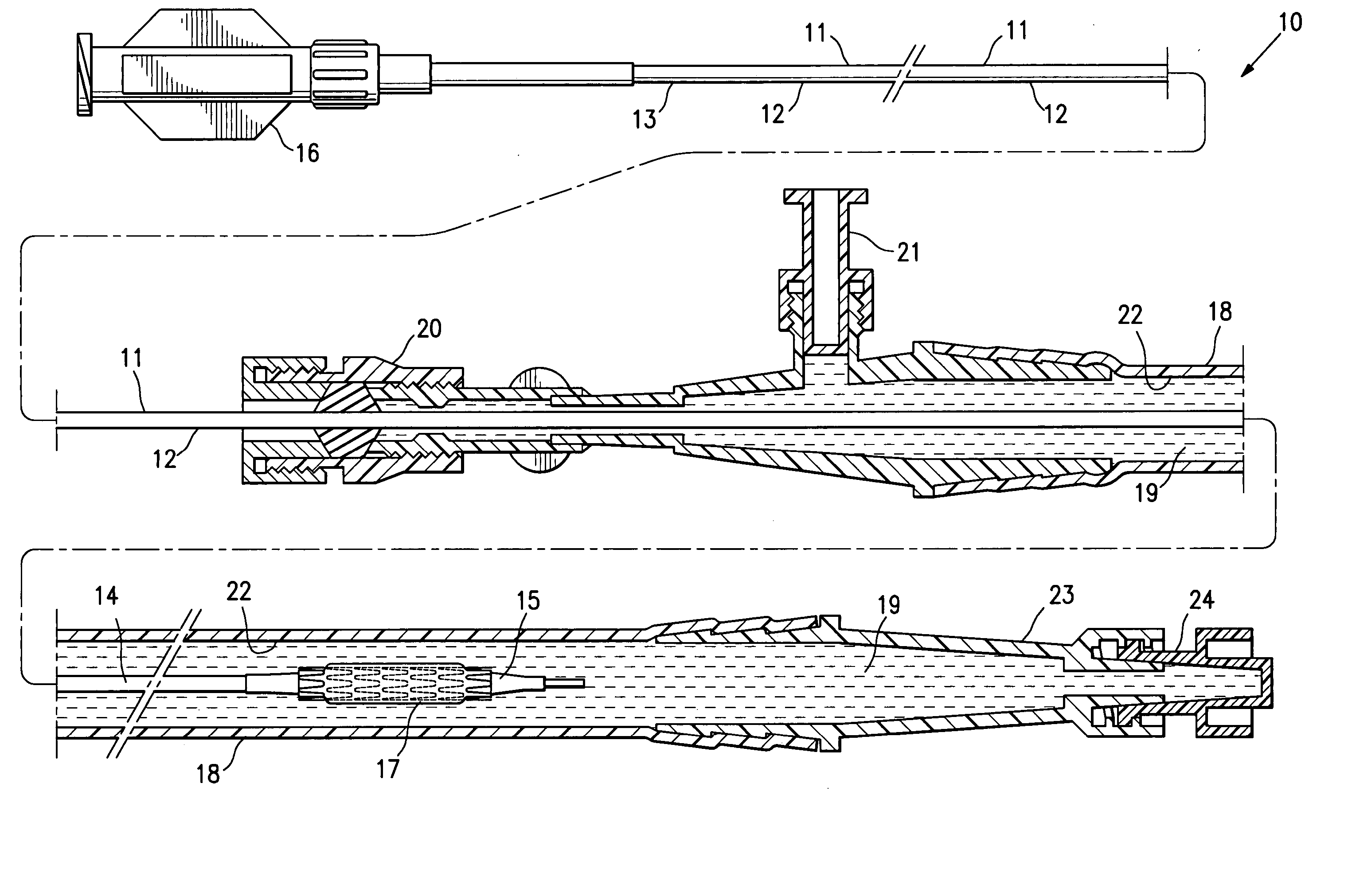
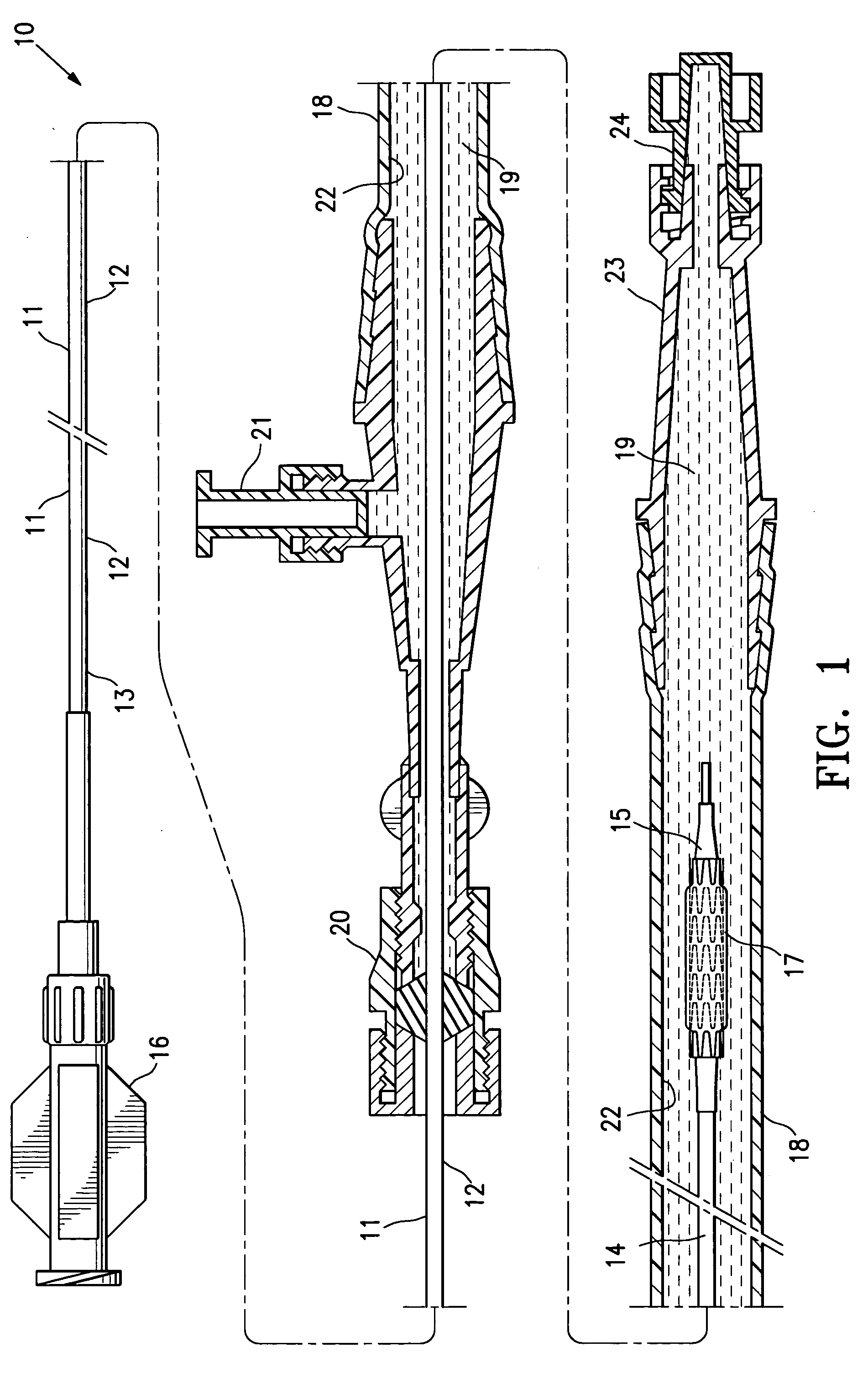
[0036]FIG. 1 illustrates a protected stent delivery system 10 embodying features of the invention. The system 10 includes a delivery catheter 11 which has an elongated shaft 12 with a relatively stiff proximal shaft section 13, a flexible distal shaft section 14, an inflatable balloon 15 on the distal section and an adapter 16 mounted on the proximal end of the elongated shaft. An expandable stent 17 is mounted on the working section of the balloon 15. A protective sheath 18 is disposed about the distal shaft section 14. The protective sheath 18 is filled with a body of protective fluid 19 which minimizes detrimental affects to the stent 18 and allows the stent to be used by the physician upon removal from the package and possible rinsing the distal shaft section and mounted balloon before inserting into the patient. The proximal end of the sheath 18 has a hemostatic valve 20 configured to sealingly engage the exterior of catheter shaft 12. A side port 21 is also provided on the pro...


PUM


Abstract

The present invention is directed to sterile packaging systems for medical devices or components where the medical device or component (e.g. a stent) is covered at least in part with a protective sheath that is configured to maintain a body of protective fluid about the covered portion of the device or component. The protective sheath preferably has one or more ports to add fluid to or withdraw fluid from the interior of the protective sheath. The partially protected article is preferably maintained in a sterile condition within a sealed container formed at least in part of a material permeable to sterilizing gas so the protected article within the interior of the sealed container may be subjected to an atmosphere of sterilizing gas which permeates into the interior of the sealed container and sterilizes the partially protected article within the sealed container. In one embodiment a protected stent delivery system is disposed in a covered but unsealed tray which in turn is sealed within a pouch formed at least in part of a material which is permeable to the sterilizing gas.

Description

BACKGROUND OF THE INVENTION [0001] The present invention relates to the delivery of expandable endoprosthesis devices, generally called stents, which are adapted to be implanted into a patient's body lumen, such as a blood vessel, to maintain the patency thereof. Stents are particularly useful in the treatment and repair of blood vessels after or during percutaneous transluminal coronary angioplasty (PTCA), percutaneous transluminal angioplasty (PTA), or atherectomy and reduce the possibility of restenosis. They may also be employed to treat vulnerable plaque. [0002] Stents are cylindrically shaped, usually metallic tubular devices which function to hold open and sometimes expand a segment of a blood vessel or other body lumen, such as coronary artery. Stents are usually delivered in a compressed condition to the target site and then deployed at that location into an expanded condition to support the vessel and help maintain it in an open position. They are also suitable for use to ...

Claims


Application Information

Patent Timeline
IPC IPC(8): A61F2/00A61F2/82A61L2/20
CPCA61F2/0095A61F2/82A61F2/958A61L2/081A61L2/087A61L2202/24A61L2/20A61L2/206A61L2/208A61L2/26A61L2/10
Inventor VONDERWALDE, CARLOS
Owner DESIGN & PERFORMANCE CYPRUS
Why Eureka
Try Eureka