Detonation engine and flying object provided therewith

a technology of detonating engine and flying object, which is applied in the direction of machines/engines, mechanical equipment, intermittent jet plants, etc., can solve the problems of complex overall engine structure, inability to obtain continuous output, and complicated overall engine structure, so as to achieve simplified overall engine structure and continuous output

Inactive Publication Date: 2005-12-29
MITSUBISHI HEAVY IND LTD +2
View PDF8 Cites 36 Cited by
  • Summary
  • Abstract
  • Description
  • Claims
  • Application Information

AI Technical Summary

Benefits of technology

[0007] The present invention takes the above situation into consideration, with an object of providing a detonation engine wherein the overall engine structure can be simplified, and continuous output can be obtained.

Problems solved by technology

However, in the pulse detonation engine disclosed in Document 1 there is a problem in that: when the outlet valve is closed, the closed valve becomes resistive; the overall engine structure becomes complicated due to providing such an outlet valve; and exhaust due to fuel replenishment, combustion, and expansion waves is performed repeatedly at a cycle of about 10 Hz to 100 Hz, and hence continuous output cannot be obtained.
However a plurality of shock tubes must be provided, and hence there is still the problem of complicated overall engine structure.

Method used


Image

  • Detonation engine and flying object provided therewith
  • Detonation engine and flying object provided therewith
  • Detonation engine and flying object provided therewith

Examples


first embodiment

[0025] Hereunder is a description of a detonation engine according to the present invention with reference to the drawings. However of course the present invention is not to be considered limited to this.

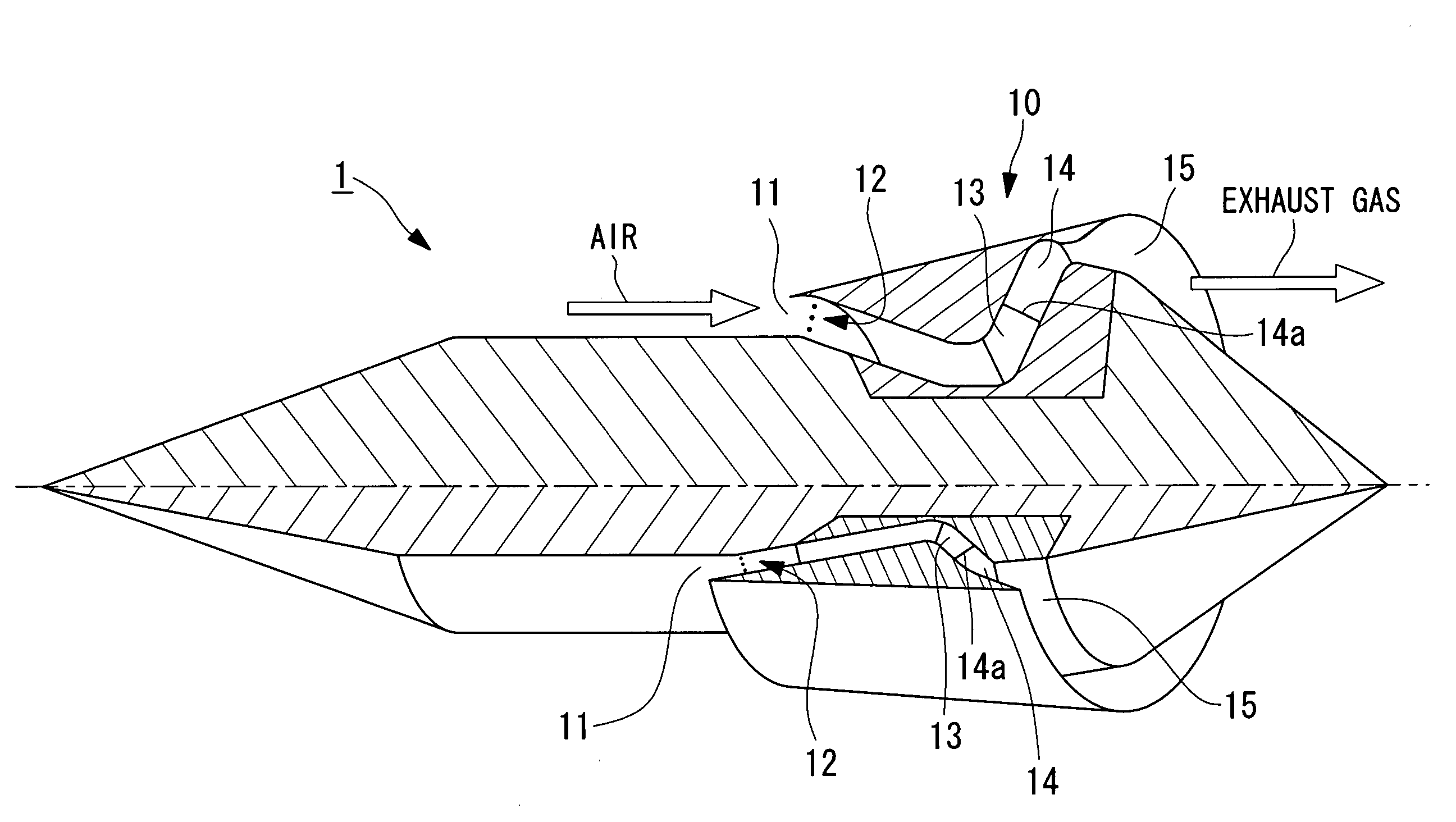
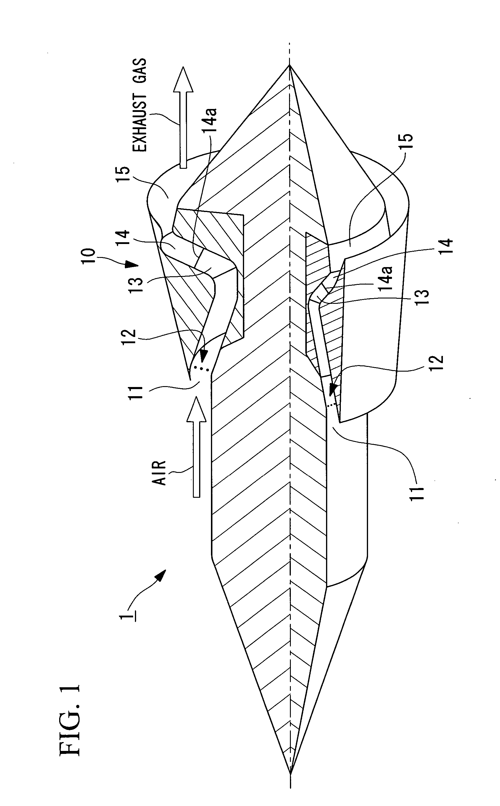
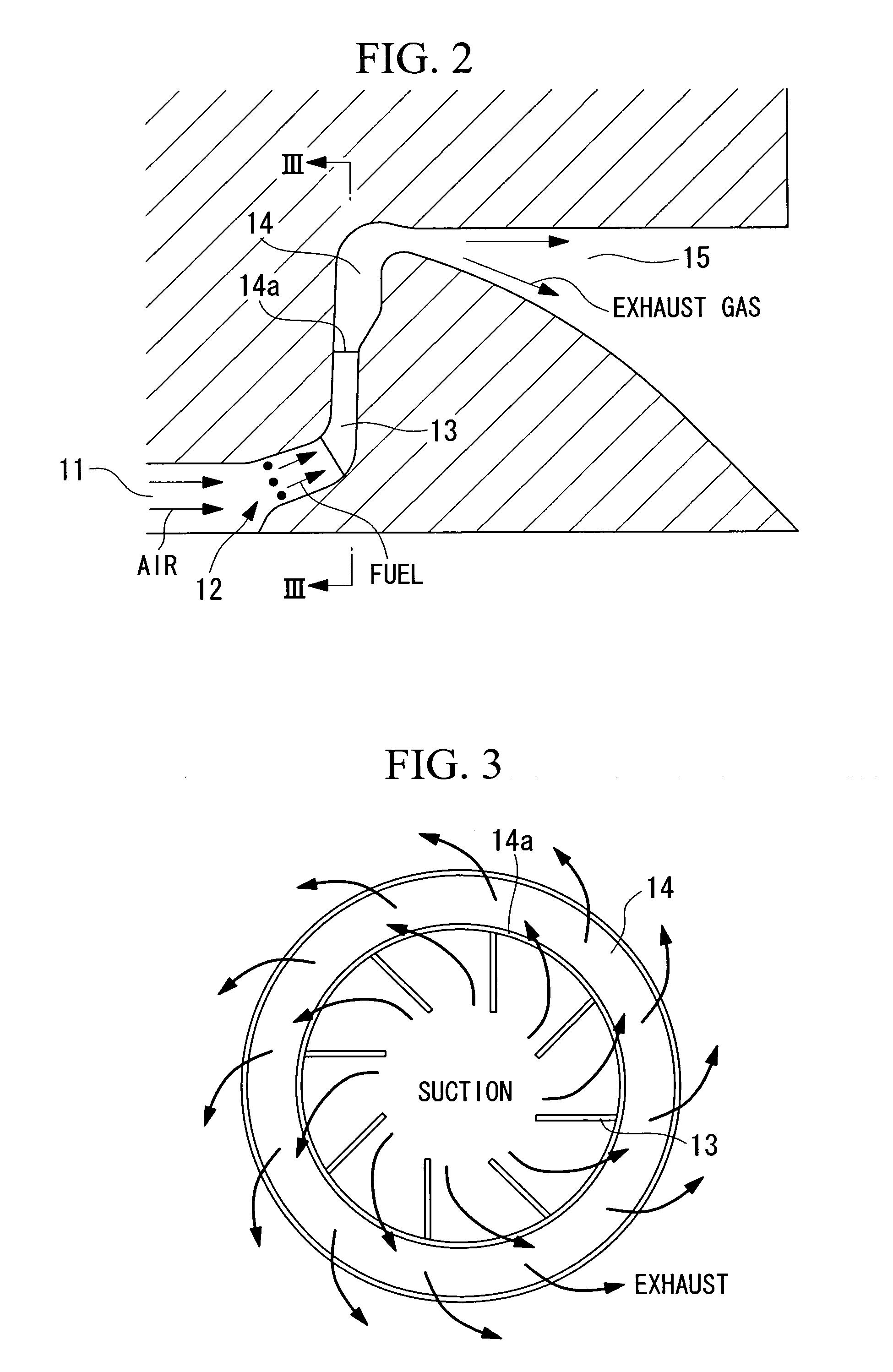
[0026]FIG. 1 is a perspective cross-sectional view showing a flying object (for example, missile, rocket, aircraft, or the like) 1 comprising a detonation engine 10 of the present embodiment. FIG. 2 is a cross-sectional view of the main parts of the detonation engine 10 shown in FIG. 1. FIG. 3 is a cross-sectional view taken along the line III-III of FIG. 2.

[0027] As shown in FIG. 1 and FIG. 2, the detonation engine 10 according to the present embodiment comprises; an inlet 11, a fuel injection nozzle 12, entrance side guide vanes (rotational flow generation device) 13, a detonation chamber 14, and a nozzle 15, as the main components.

[0028] The inlet 11 is an air intake for taking in the combustion air (atmosphere) into the detonation engine 10. This inlet 11 becomes subsonic or s...

second embodiment

[0048] the detonation engine according to the present invention is described using FIG. 4.

[0049]FIG. 4 is similar to FIG. 2, being a cross-sectional view of the main parts of the detonation engine 20 according to the present embodiment.

[0050] As shown in FIG. 4, the detonation engine 20 according to the present embodiment comprises; an inlet 11, a fuel injection nozzle 12, a detonation chamber 14, a nozzle 15, a turbine nozzle 21, and a turbine rotor 22, as the main components.

[0051] Since the inlet 11, the fuel injection nozzle 12, the detonation chamber 14, and the nozzle 15 have already been explained for the first embodiment, explanation thereof is omitted here.

[0052] The turbine nozzle 21 comprises; a plurality of nozzle guide vanes having an airfoil cross section which are arranged annularly, and has a function to expand and decompress the gas flowing out from the detonation chamber 14, and to change the flow direction of the gas flowing out from itself so that it can impin...

third embodiment

[0059] the detonation engine according to the present invention is described using FIG. 5.

[0060]FIG. 5 is similar to FIG. 1, being a perspective cross-sectional view showing a flying object (for example, missile, rocket, aircraft, or the like) 2 comprising a detonation engine 30 of the present embodiment.

[0061] As shown in FIG. 5, the detonation engine 30 according to the present embodiment comprises; an inlet 11, a fuel injection nozzle 12, entrance side guide vanes 13, a detonation chamber 14, a nozzle 15, a turbine rotor 31, and an outer casing 32, as the main components.

[0062] Since the inlet 11, the fuel injection nozzle 12, the detonation chamber 14, and the nozzle 15 have already been explained for the first embodiment, explanation thereof is omitted here.

[0063] The turbine rotor 31 comprises; a disk 33, turbine blades 34, and a fan 35. The turbine blades 34 are provided radially outside of the disk 33. The fan 35 is provided radially outside of the turbine blades 34. More...


PUM

PropertyMeasurementUnit
thrustaaaaaaaaaa
angleaaaaaaaaaa
temperatureaaaaaaaaaa

Abstract

A detonation engine which creates thrust by generating a detonation wave, wherein the overall engine structure is simplified, and continuous output can be obtained, comprises: a rotational flow generation device which generates rotational flow about an axis in a mixed gas of air and fuel or of oxygen and fuel; a detonation chamber arranged downstream from the rotational flow generation device, formed in a ring-shape radially extended and continuous in the circumferential direction, which continuously combusts in the circumferential direction the mixed gas in which the rotational flow is generated to generate detonation waves, and draws it in from the radial inside and exhausts it to the radial outside; and a nozzle which is connected to the detonation chamber, and jets the high temperature and pressure combustion gas generated by the detonation waves flowing from the detonation chamber, to the rear while expanding it, and converts it into thrust.

Description

BACKGROUND OF THE INVENTION [0001] 1. Field of the Invention [0002] The present invention relates to a detonation engine which utilizes the detonation phenomenon accompanying a normal shock wave at the front of a combustion wave. [0003] 2. Description of Related Art [0004] As a detonation engine which utilizes the detonation phenomenon, there is known a pulse detonation engine comprising an outlet valve at the exit of the combustion tube (for example, refer to Takayuki Kojima, “Conceptual Study on Application of PDE to Hypersonic Propulsion system”, the proceedings of Symposium on Shock Waves, 2003 Japan, p. 113 to 116 (hereunder, “Document 1”)), and a combined cycle pulse detonation turbine engine comprising a plurality of shock tubes (for example, refer to Japanese Unexamined Patent Application, First Publication No. 2001-355515 (FIG. 1 and FIG. 2) (hereunder, “Document 2”)). [0005] However, in the pulse detonation engine disclosed in Document 1 there is a problem in that: when th...

Claims


Application Information

Patent Timeline
Patent Type & Authority Applications(United States)
IPC IPC(8): C23C4/12C23C24/04F01D5/02F02C3/14F02K3/04F02K5/02F02K7/00F02K7/02
CPCC23C4/122C23C24/04F02K7/02F02K3/04F02K7/00F01D5/022C23C4/126
Inventor TOBITA, AKIHIROFUJIWARA, TOSHITAKAWOLANSKI, PIOTR
Owner MITSUBISHI HEAVY IND LTD
Why Eureka
Try Eureka