Flywheel Engine

a technology of flying wheels and propellers, which is applied in the direction of machines/engines, gas turbine plants, mechanical equipment, etc., can solve the problems of congenital defects in technology, increase equipment costs, and complicated equipment manufacturing, so as to improve the energy utilization ratio, reduce the effect of consumption and more fuel

Inactive Publication Date: 2010-12-09
JINAN METAL HABER METALLURGICAL TECH DEV
View PDF8 Cites 6 Cited by
  • Summary
  • Abstract
  • Description
  • Claims
  • Application Information

AI Technical Summary

Benefits of technology

[0010]The advantages of the present invention lie in: It adopts brand new ways of thermal energy conversion, makes full use of circular motion and fluid motion, overcomes the problems that exist in the former engines, consumes less energy during the intermediate links, improve the energy usage ratio, burns the fuel more fully. It could discharge less harmful gases and could be more environmentally friendly. It improves the engine's power output incalculably and simplifies the structure of the engine greatly. It creates high temperature and high pressure environment which brings about conditions that could prepare all kinds of materials. The present invention's merits also include simplified manufacture, low cost, high energy usage ratio, energy-conserving and environment-protective and etc.

Problems solved by technology

The existing methods of thermal energy conversion, the method of thermal energy converts to kinetic energy takes complex structures in which the intermediate links bring about too much energy dissipation and low energy conversion which complicate the equipment manufacturing, rise the equipment cost, set down the capacity usage ratio and result in congenital defects in technology, all these factors make it is hard to break through the technical bottleneck.
Manufacturing methods of high temperature and high pressure also confront the problems of achieving higher temperatures and high pressures, and a great variety of materials cannot be produced for this reason.
Due to the principle congenital defects of the internal-combustion engines, they have lots of defects such as large weight, low speed of revolution, high energy consumption, large amount of discharges, loud noise, high cost, high maintenance cost, short service life and other defects.
Jet engines also have many defects as small thrust force, low jet velocity, high cost, high energy consumption, large discharge of noxious gas, high maintenance cost, and short service life and so on.
With complex structures, inter mediate links bring about too much energy dissipation and low energy conversion.
With congenital defects of design theory of internal-combustion engines, even the technology is very mature nowadays, it is hard to overcome the difficult problem of the low capacity usage ratio.
The existing equipments which can create high temperature and high pressure environment cannot provide higher temperature and pressure.
They also have other defects such as the complexity of the equipments, high energy consumption, high cost and so on.
All these defects cause the failure creation of conditions which can be used to manufacture artificial stones and other new materials.

Method used


Image

  • Flywheel Engine
  • Flywheel Engine
  • Flywheel Engine

Examples


first embodiment

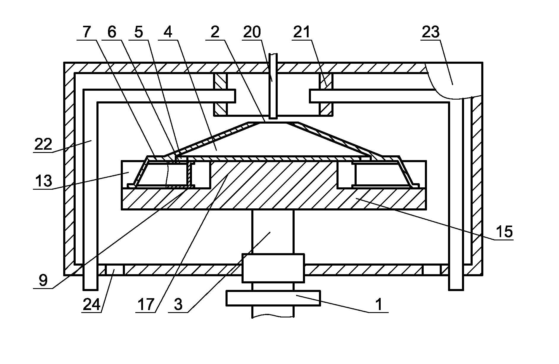
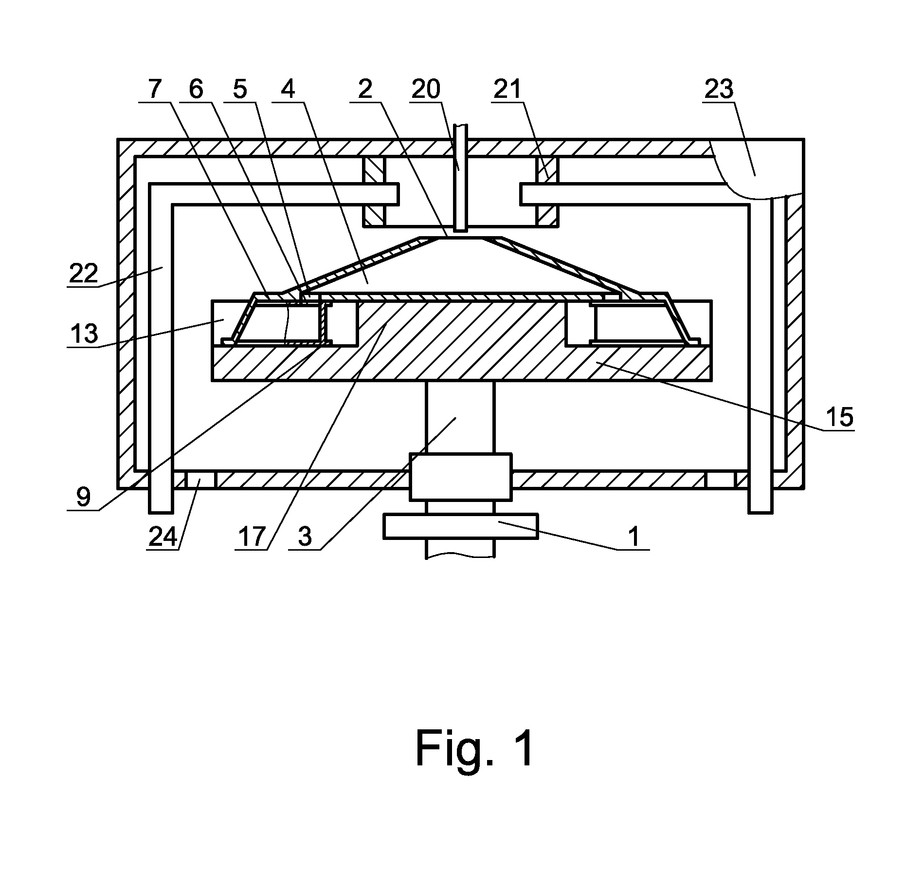
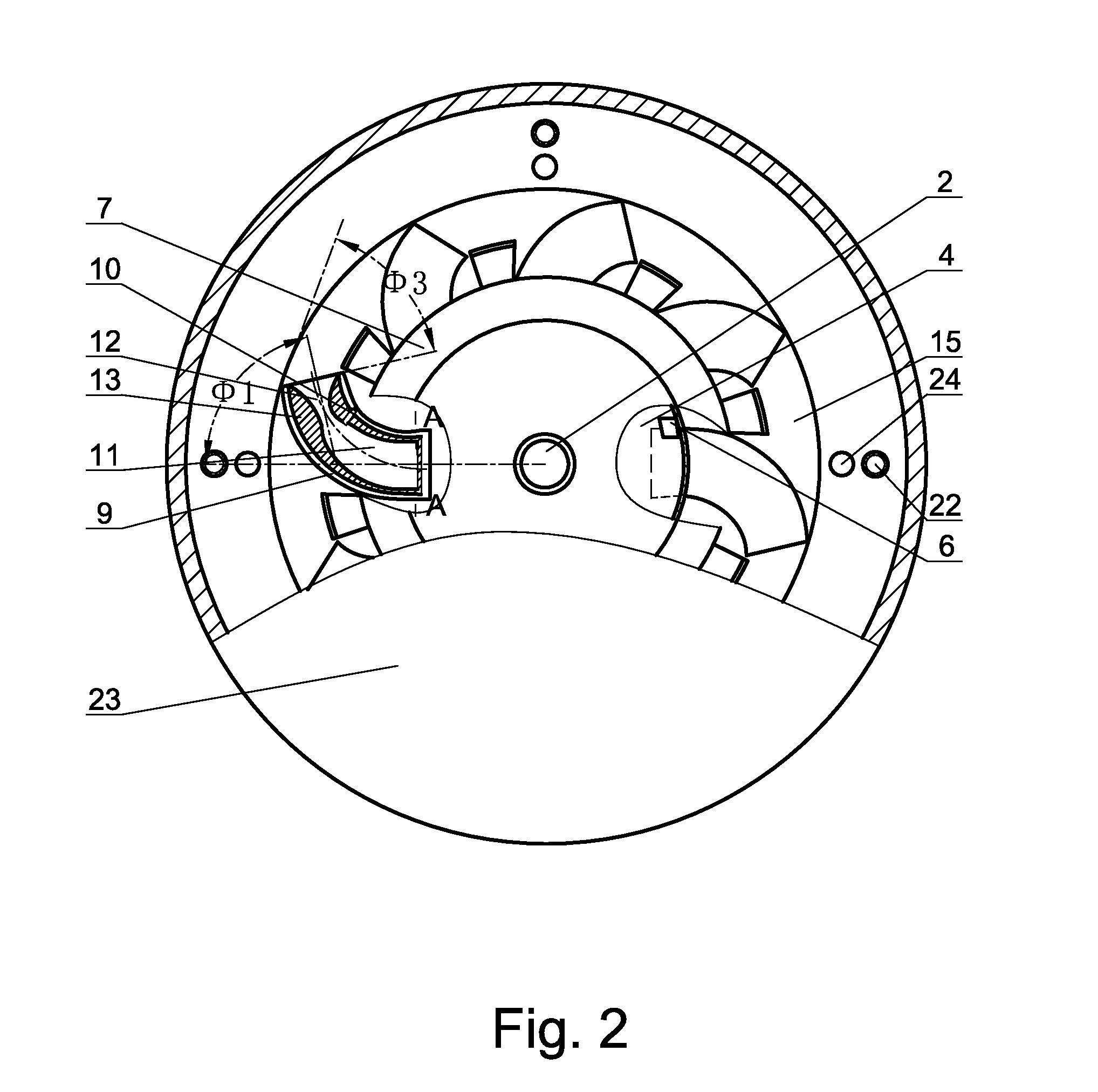
[0046]The structure of the present invention is: install air cylinder at the peripheral region of flywheel 15, upper admittance port 6 is set on an superior wall located at a bottom portion of the air cylinder, while under part jet exhaust 5 is set on a inferior wall located at the peripheral region of gas mixture room 4, upper admittance port 6 is connected with under part jet exhaust 5. The monolithic structure of the embodiment is firm and can fasten gas mixture room 4 and flywheel 15 together. The high integrated intensity can better realize the high speed rotating of the engine. In order to increase the integrated intensity, a raised boss 17 can be created on the surface of flywheel 15 then install gas mixture room 4 above boss 17 and make the edge of gas mixture room 4 cover the admittance port of the air cylinder. Make the opening of inlet pipe 18 on the air cylinder lean towards to the upward side of flywheel 15's surface and opens to gas mixture room 4. Fasten gas mixture r...

second embodiment

[0047]Structure of the second embodiment is: set gas mixture room 4 at the center of flywheel 15, under part admittance port 61 is set on an inferior wall located at a bottom portion of the air cylinder, while upper jet exhaust 51 is set on a superior wall located at the periphery of the gas mixture room 4, then connect under part admittance port 61 and upper jet exhaust 51. The installation of this embodiment is quite simple.

third embodiment

[0048]Structure of the third embodiment is: open lateral jet exhaust 52 on the side wall of gas mixture room 4 and open lateral admittance port 62 at the bottom's lateral surface of the air cylinder. According to the demand of the rotating speed of flywheel 15, set admittance port at the plus side or the reversal side at the bottom of the air cylinder. This installation is relatively more complex and the effect is not ideal. Inlet pipe 18 parallels to the surface of flywheel 15 and twistingly opens to gas mixture room 4. In order to further improve the inlet pressure, the inner cavity of inlet pipe 18 is gradually enlarged and opened to the direction of gas mixture room 4. The defect of this embodiment is inlet pipe employs part of the space which brings about the reduction of air cylinders' installation. Therefore, the effect is not ideal either.

[0049]In order to improve the force supplies by the flywheel engine and save the cost, gas mixture room 4 is installed at the upper and lo...


PUM


Abstract

The present invention publishes a flywheel engine which contains the shell, ignition system, cranking system and fuel system. Install flywheel shaft on shell while at least install a flywheel on the flywheel shaft. Set up gas mixture room on flywheel and open air inlet louver at the middle part of the room. Install air cylinder at the peripheral region of flywheel and open jet exhaust at the peripheral region of gas mixture room. Set up admittance port at the bottom of the air cylinder; connect the admittance port and the jet exhaust. Install flame lighter in the air cylinder. The angle of the jet direction of chambers and the radius of flywheel is Φ1. The advantages of the present invention includes: Consumes less energy during the intermediate links, improve the energy usage ratio, burns the fuel more fully. It could discharge less harmful gases and could be more environmentally friendly. It improves the engine's power output incalculably and simplifies the structure of the engine greatly. It creates high temperature and high pressure environment which brings about conditions that could prepare all kinds of materials.

Description

FIELD OF THE INVENTION[0001]The present invention which relates to the field of power equipment and thermodynamic equipment is a kind of flywheel engine.BACKGROUND OF THE INVENTION[0002]The existing methods of thermal energy conversion, the method of thermal energy converts to kinetic energy takes complex structures in which the intermediate links bring about too much energy dissipation and low energy conversion which complicate the equipment manufacturing, rise the equipment cost, set down the capacity usage ratio and result in congenital defects in technology, all these factors make it is hard to break through the technical bottleneck. Manufacturing methods of high temperature and high pressure also confront the problems of achieving higher temperatures and high pressures, and a great variety of materials cannot be produced for this reason.[0003]The existing engines are mainly internal-combustion engine and jet engine. Due to the principle congenital defects of the internal-combus...

Claims


Application Information

Patent Timeline
Patent Type & Authority Applications(United States)
IPC IPC(8): F02C3/16
CPCF02C3/165
Inventor CHEN, JIUBIN
Owner JINAN METAL HABER METALLURGICAL TECH DEV
Why Eureka
Try Eureka