
Self-locking carbon adsorbed body

Inactive Publication Date: 2005-12-29
JAPAN SCI & TECH CORP +1
View PDF0 Cites 3 Cited by
  • Summary
  • Abstract
  • Description
  • Claims
  • Application Information

AI Technical Summary

Benefits of technology

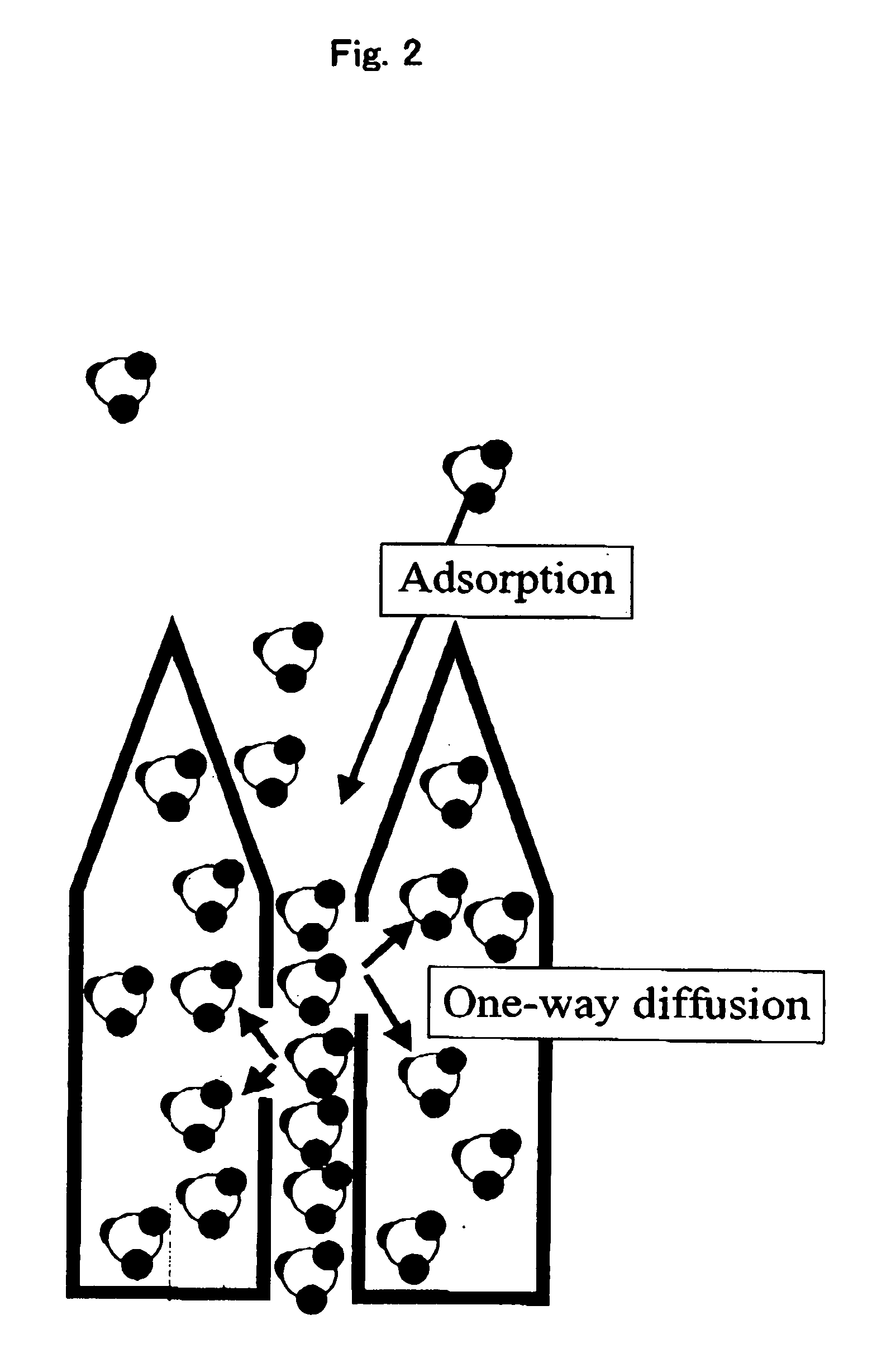
[0008] Specifically, the invention of the patent application provides, first, a self-locking carbon adsorbent comprising a carbon nanohorn aggregate provided with one or more openings in the wall part thereof, wherein a substance to be adsorbed passes through the opening in one limited direction from the outside to inside of the carbon nanohorn in isothermal or isobaric adsorption.
[0009] With regard to the method of the above invention, the invention of the patent application provides, second, a self-locking carbon adsorbent wherein the substance to be adsorbed is gas which is put in a supercritical state at room temperature, third a self-locking carbon adsorbent wherein the substance to be adsorbed is methane gas and the methane gas is allowed to be adsorbed in a quasi-liquid state in the inside of the carbon nanohorn, and fourth a self-locking carbon

Problems solved by technology

However, this liquefied natural gas has the drawback that it must be kept at extreme low temperature as low as −160° C. or less during all processes such as storage and transfer and therefore has a difficulty in putting it to practical use.
However, this target has not been achieved yet.

Method used


Image

  • Self-locking carbon adsorbed body
  • Self-locking carbon adsorbed body
  • Self-locking carbon adsorbed body

Examples


example 1

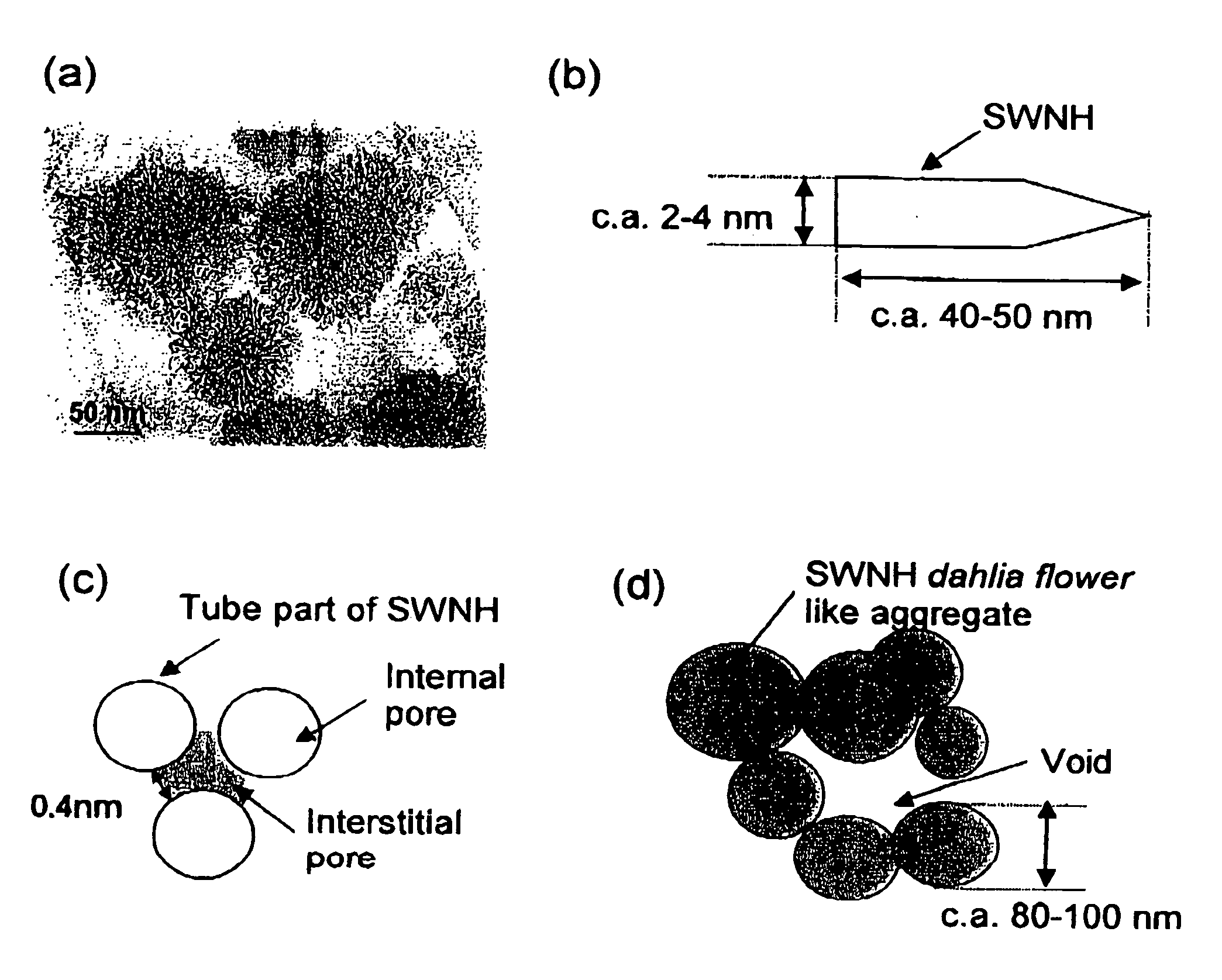
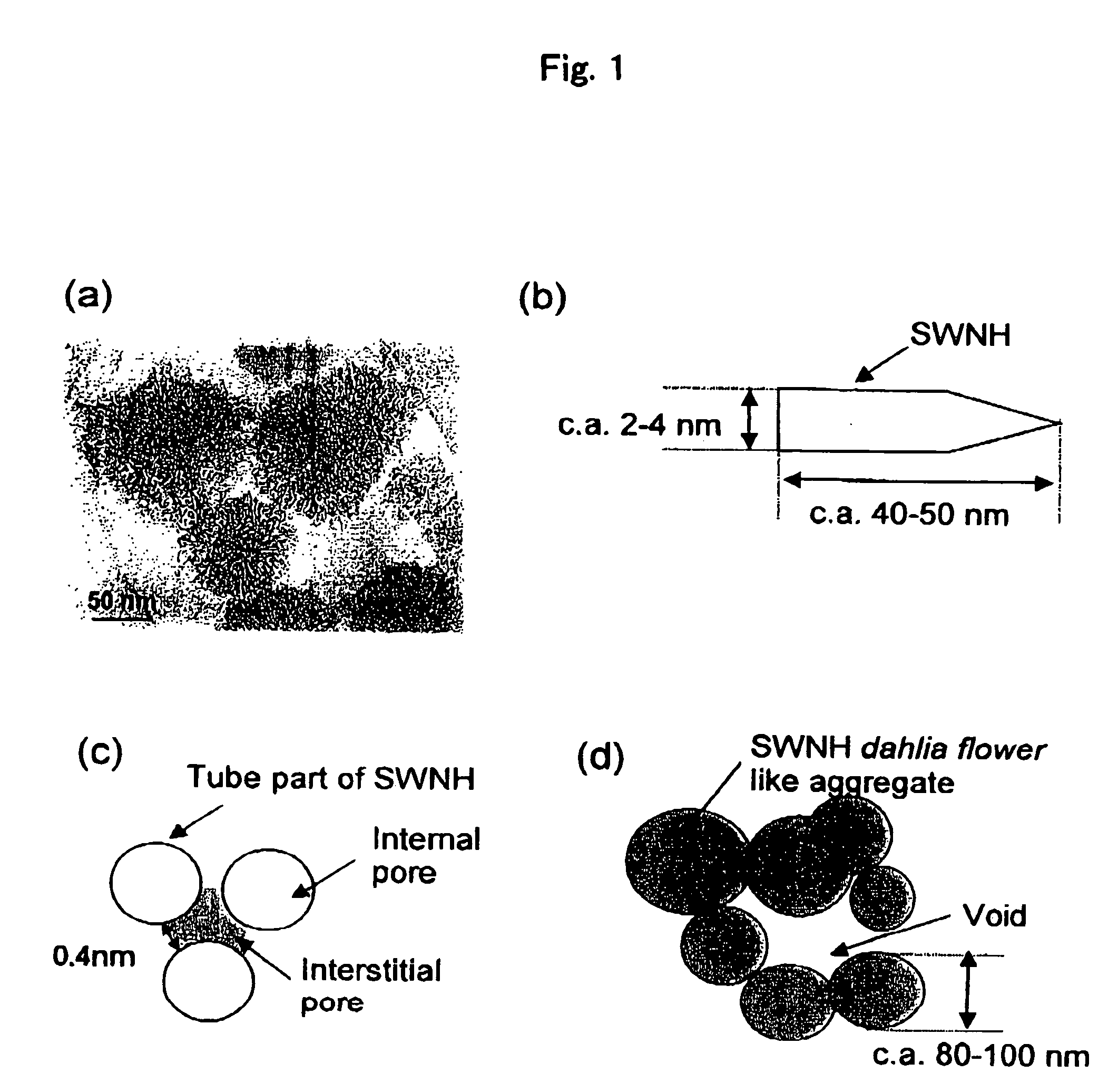
[0029] The isothermal adsorption characters of a dahlia-like carbon nanohorn (SWNH), carbon nanohorn (opened SWNH) provided with openings on the tube wall or the tip part of the above dahlia-like carbon nanohorn by oxidation beating treatment, activated carbon fiber (ACF) and KOH activated carbon (AX21) were measured. Prior to the measurement, the SWNH and the opened SWNH were treated under heating at 423 K under a pressure of 1 mPa to remove adsorbed gas and moisture.

[0030] The methane adsorption characters of the SWNH, opened SWNH, ACF and AX21 were measured at 303 K under a pressure range from 10 kPa to 10 MPa by utilizing an electronic balance. The interstitial pore structures of these materials were estimated from N2 adsorption isotherm at 77 K by utilizing a SPE method (subtracting pore effect method) which subtracts the effect of fine pores. Moreover, with regard to the correlation characteristic between CH4 and the SWNH, that of the interstitial pore and the internal pore w...

example 2

[0042] The hydrogen adsorption characters of a carbon nanohorn (opened SWNH) provided with openings in the tube wall or the tip part by subjecting a dahlia-like carbon nanohorn to oxidation heat treatment were investigated. Prior to the measurement of adsorption, the opened SWNH was heat-treated at 423 K under a pressure of 1 mPa or less to remove adsorbed gas and moisture.

[0043] The hydrogen isothermal adsorption characters of the opened SWNH were measured using an electronic balance at three temperatures 77 K, 196 K and 303 K under pressure ranging from 10 kPa to 10 MPa. The results are shown in FIG. 6.

[0044] Also, using a carbon tube having the same tube diameter, a simulation using a computer was carried out to estimate the amount of hydrogen to he stored theoretically and the results are also shown together. This theoretical estimation has been confirmed to conform to the amount to be stored in an experiment made for a carbon material having silt type pores sandwiched between...


PUM

PropertyMeasurementUnit
Temperatureaaaaaaaaaa
Pressureaaaaaaaaaa
Temperatureaaaaaaaaaa

Abstract

The invention relates to a new self-locking carbon adsorbent comprising a carbon nanohorn aggregate provided with an opening in the wall part thereof, wherein a substance to be adsorbed passes through the opening in one limited direction from the outside to inside of the carbon nanohorn in isothermal or isobaric adsorption, whereby the self-blocking carbon adsorbent is made to be useful, for example, for storing methane gas and can store various gases at room temperature at a high density.

Description

TECHNICAL FIELD [0001] The invention of the patent application relates to a self-locking carbon adsorbent. The invention of the patent application relates, particularly to a new self-locking carbon adsorbent which is useful for storing methane gas and can store various gases put in a high density as quasi-liquid state at room temperature. BACKGROUND ART [0002] Much attention is focused on natural gas as clean energy which takes the place of petroleum oil from the viewpoint of preservation of the global environment and effective utilization of resources. The density of methane gas which Is a major component of natural gas is 23 g / L at 303 K under 3.5 MPa but is as very high as 419 g / L at its boiling point or 109 K. Liquefied natural gas is, based on this characteristics, cooled under pressure to liquefy after it is refined into a methane component as a major component and supplied as highly refined liquefied natural gas called refrigerated liquid methane (RLM). [0003] However, this l...

Claims


Application Information

Patent Timeline
IPC IPC(8): B01J20/20C01B31/02
CPCB01J20/205B01J20/20
Inventor IIJIMA, SUMIOYUDASAKA, MASAKOMURATA, KATSUYUKIKANEKO, KATSUMIKASUYA, DAISUKE
Owner JAPAN SCI & TECH CORP
Learn More