Focusing of microscopes and reading of microarrays

a microarray and microscope technology, applied in the field of microscope focusing and microarray reading, can solve the problems of unattended operation of such instruments, high cost, economic and operational drawbacks, etc., and achieve the effect of low cos

Inactive Publication Date: 2005-12-29
AFFYMETRIX INC
View PDF74 Cites 12 Cited by
  • Summary
  • Abstract
  • Description
  • Claims
  • Application Information

AI Technical Summary

Benefits of technology

[0014] The present invention provides a novel method and system for focusing a microscope. Though, at its broadest level of generality, it is applicable to all microscopes, it has particular advantage when associated in a system for automatic focusing, and it is presently considered most advantageous when the automatic focusing system is associated with a scanning system in which the object under inspection is translated under either a fixed or moving lens. The invention is especially applicable to instrument systems that operate under computer control such as optical scanners designed for reading biochips constructed on microscope slides or incorporated in a holder such as the Affymetrix “Gene Chip®”. While having a special application in achieving low cost automated scanning, in which focus is established once per slide, the invention is also advantageous in performing dynamic focus.

Problems solved by technology

In many cases this mechanism must be constructed with high accuracy to be capable of micron or sub-micron positional resolution, which results in high cost.
The large volume of data to be evaluated also calls for unattended operation of such instruments upon a sequence of slides or biochips, including automatic focusing of the microscope for each slide, biochip, or other object and in some cases, automatic focusing as scanning of a particular object proceeds.
Focusing in these instruments is commonly automated, but there are significant economic and operational drawbacks in the systems that have been commercially available.
Other types of substrates for microscopic examination, including arrays provided on relatively thin glass cover slips and on plastic substrates or holders, likewise have variation in thickness or shape and are subject to deformation or the area to be viewed does not have an accurate or reliable reference location.
Typically instruments that enable dynamic focus adjustment with great precision require great cost.
Unfortunately, such techniques have unsatisfactory aspects, in causing the slide to deform, especially with bowing.
This frequently results in loss of resolution.
Also, such technique can only be used when the surface to be inspected is rigid and co-planar with the buttress reference location.

Method used


Image

  • Focusing of microscopes and reading of microarrays
  • Focusing of microscopes and reading of microarrays
  • Focusing of microscopes and reading of microarrays

Examples


Embodiment Construction

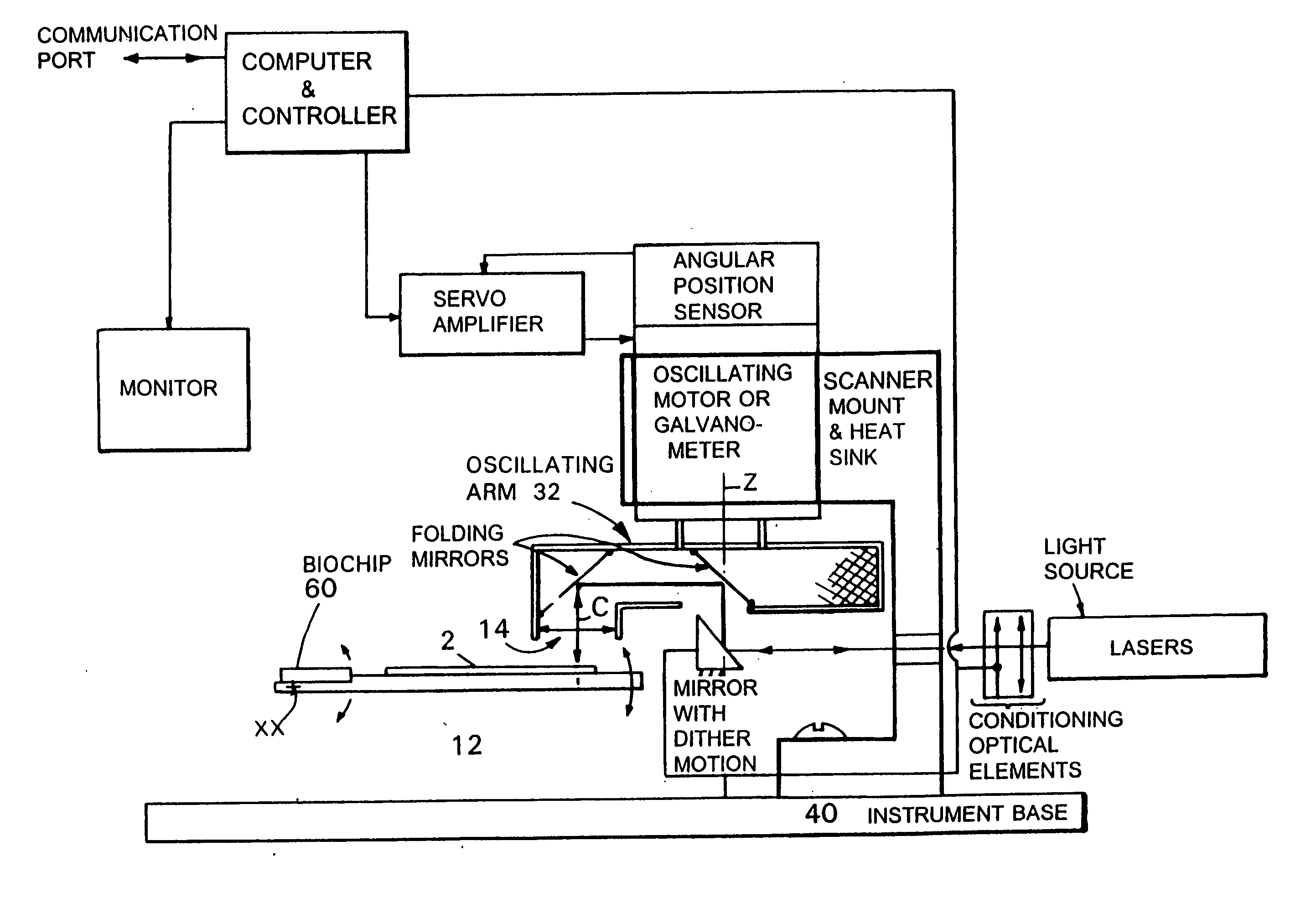
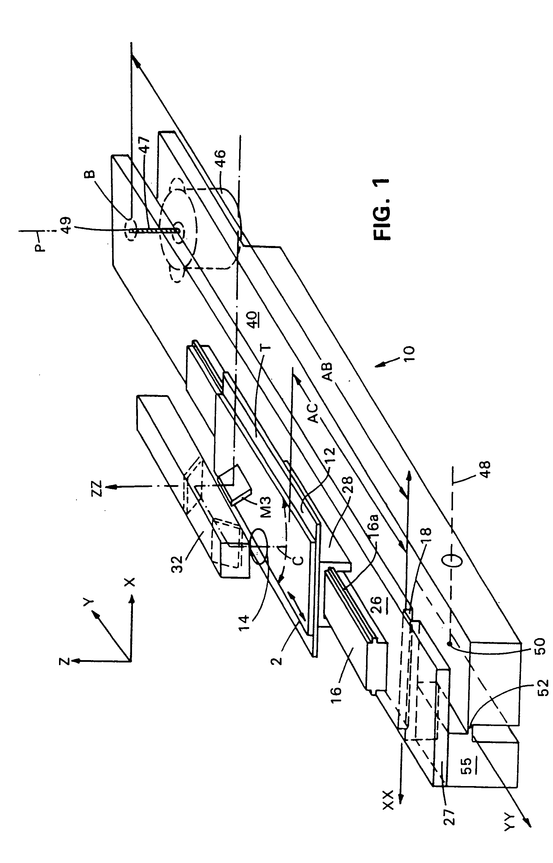
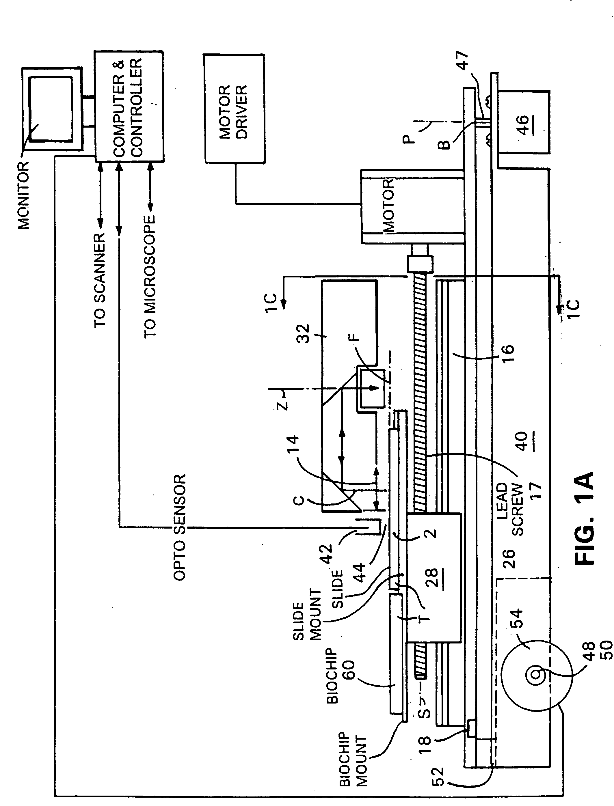
[0071] The invention will be described as it applies to the presently preferred embodiment, which includes, in combination, a rotary oscillating flying micro-objective scanning microscope such as shown in FIG. 2 and described in more detail in the patent applications related to scanning cited above, which are hereby incorporated by reference.

[0072] Referring to FIGS. 2 and 2A, it is sufficient to note that objective-carrying arm 32 rotates in rotary oscillating fashion through an arc of e.g. 60 degrees about rotational axis ZZ that is normal to the nominal plane of the microscope slide 2 or biochip 60. The arm carries a low mass micro-objective lens 14, e.g. a micro lens of weight less than about 2 grams, sized to detect a single picture element at any data collection point. The optical axis C at a radial distance from the axis of rotation ZZ, produces a range of excursion E sufficient to scan the width of the microscope slide 2 or biochip 60, provision for both of which are provid...


PUM

PropertyMeasurementUnit
diametersaaaaaaaaaa
thickaaaaaaaaaa
depth of fieldaaaaaaaaaa

Abstract

Microscopes, including viewing and other microscopic systems, employ a hinged, tiltable plate to adjust focus on a flat object such as a microscope slide or biochip by motion, achieved by tilting, which is substantially normal to the focus point on the plane of the object. By employing two such tiltable arrangements, relatively long scan lines of e.g., flying objective, single pixel on-axis scanning can be accommodated. The tilting support plate is specifically constructed to provide tailored locations for different objects in series along the Y axis of the plate. The plate can accommodate heaters and cooled plates and/or the flat object being examined. In a fluorescence scanning microscope, locations are specifically adapted to receive microscope slides and biochip cartridges such as Affymetrix's “Gene Chip®”. A scanning microscope under computer control, employing such a focusing action, enables unattended scanning of biochips with a simple and economical instrument. Also shown are flexure-mounting of a support plate to define the hinge axis, techniques for automatically determining position and focus, and a rotatably oscillating flying micro-objective scanner combined with the tilting plane focus system. Construction and control techniques are shown that realize simple and accurate focusing. Methods of examination of biological materials are disclosed. Simple and efficient focused scanning with a flying micro-objective of ordered arrays of nucleotides and nucleic acid fragments carried upon a microscope slide or other substrate is disclosed. Quantified fluorescence imaging is economically achieved by combined use of the described scanning and focusing arrangement and use of simple and accurate calibration modules respectively for example for Affymetrix's “Gene Chip” microarray modules and for microscope slides.

Description

CROSS REFERENCE TO RELATED APPLICATIONS [0001] This application is a continuation-in-part of U.S. Ser. No. 09 / 079,790, filed May 15, 1998, entitled “Focusing Microscope Systems”; of U.S. application Ser. No. 09 / 045,547, filed Mar. 20, 1998, entitled “Wide Field Of View And High Speed Scanning Microscopy”; of U.S. Ser. No. 09 / 079,324, filed May 14, 1998, entitled “Depositing Fluid Specimens On Substrates, Resulting Ordered Arrays, Techniques For Analysis Of Deposited Arrays”; U.S. Ser. No. 09 / 122,216, filed Jul. 24, 1998, entitled “Depositing Fluid Specimens On Substrates, Resulting Ordered Arrays, Techniques For Deposition Of Arrays”; and of U.S. Ser. No. 09 / 170,847, filed Oct. 13, 1998, entitled “Wide Field Of View And High Speed Scanning Microscopy”; all of which are hereby incorporated by reference. Also incorporated by reference are International PCT / US99 / 06097 (WO99 / 47694), entitled “Wide Field Of View And High Speed Scanning Microscopy” PCT / US99 / 00730 (WO99 / 3670) Entitled”“Dep...

Claims


Application Information

Patent Timeline
Patent Type & Authority Applications(United States)
IPC IPC(8): G01N21/64G02B21/16
CPCG01N21/6428G02B21/16G01N21/6458G01N21/6452
Inventor MONTAGU, JEAN I.OVERBECK, JAMES W.
Owner AFFYMETRIX INC
Why Eureka
Try Eureka