X-ray imaging system and imaging method
a technology of x-ray imaging and imaging method, applied in the field of x-ray imaging apparatus, can solve the problems of complex configuration of the apparatus and the source of x-ray, and achieve the effect of simple construction
- Summary
- Abstract
- Description
- Claims
- Application Information
AI Technical Summary
Benefits of technology
Problems solved by technology
Method used
Image
Examples
experimental example 1
[0054] Experimental example 1 shows the occurrence of the Talbot effect due to irradiation of a diffraction grating with X-rays.
Experimental Conditions
[0055] X-rays used: light of wavelength 0.1 nm emitted by a synchrotron.
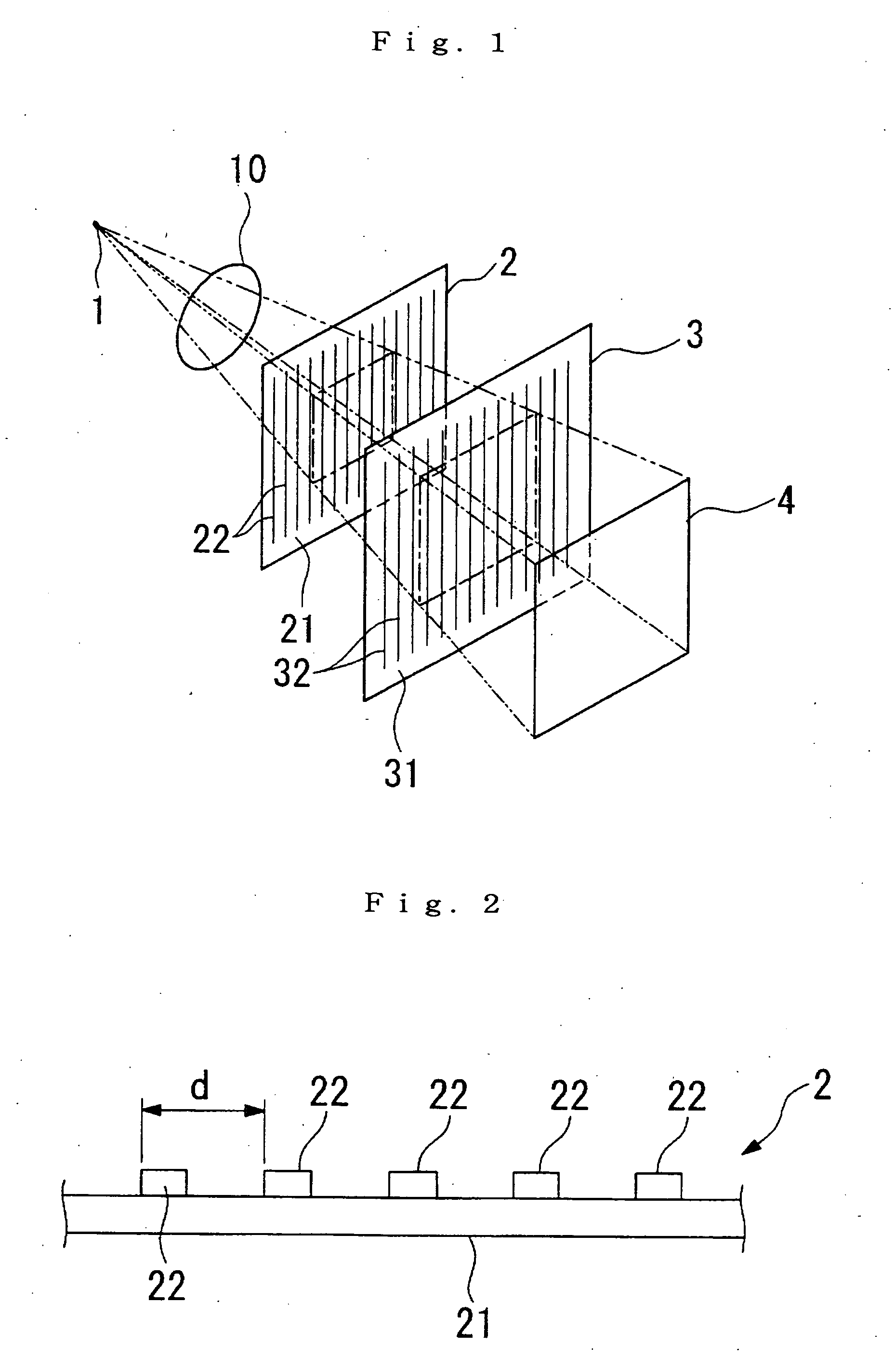
[0056] Diffraction grating: Gold pattern approximately 1 micron thick formed with a period d=8 microns on a 150 micron-thick glass plate.
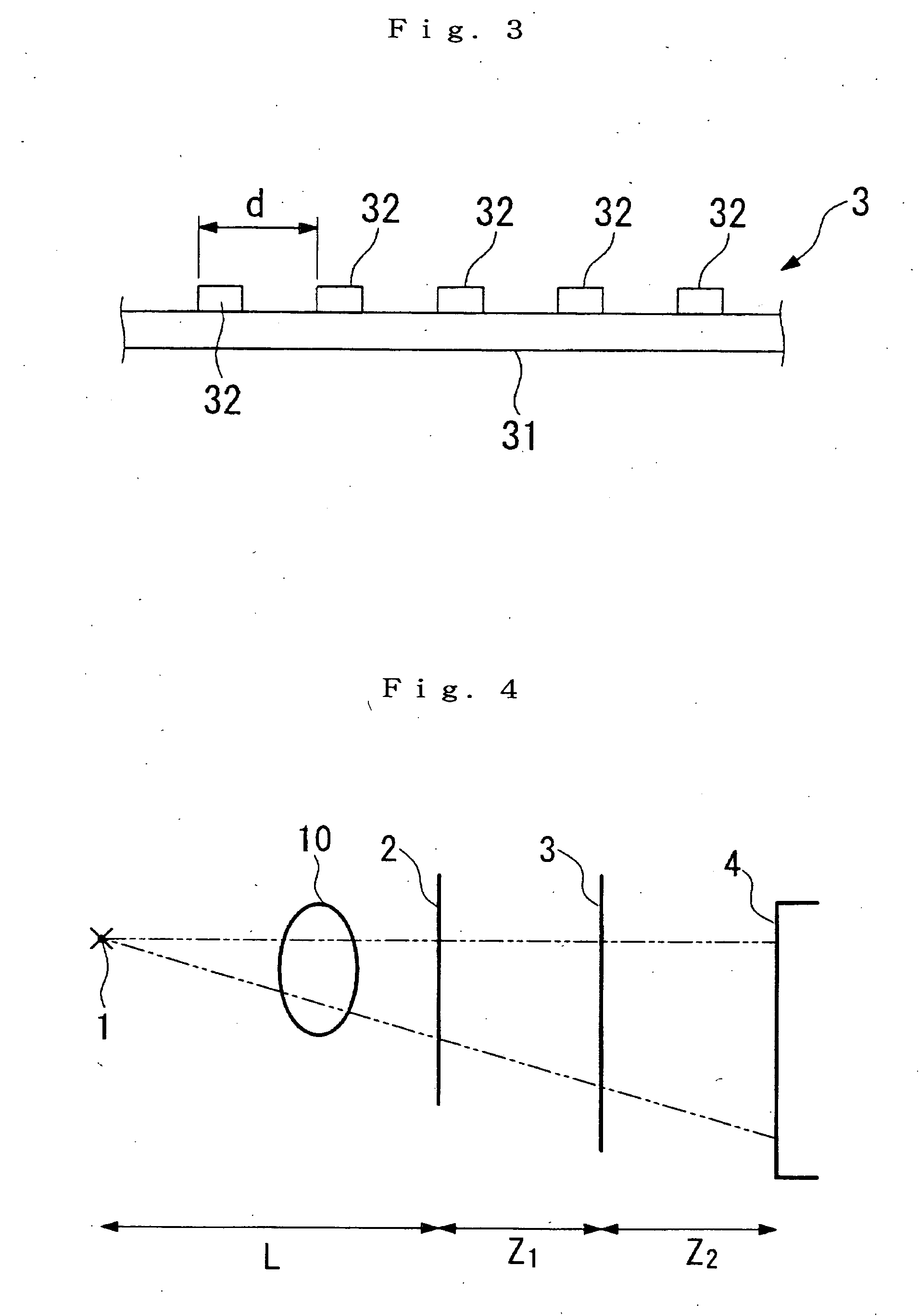
[0057] The conditions for generating the Talbot effect using phase-type diffraction gratings are: Z=(m+12) d2λ
[0058] Therefore, first, corresponding with when m=0, a self image for the diffraction grating should be formed when the distance Z from the first diffraction grating 2 to the detection surface is 32 cm. An X-ray image detector is then positioned at a position where the distance Z is 32 cm, and an image is recorded. The results are shown in FIG. 5. Similarly, when the distance Z is 64 cm, from the above conditions, this is when shifting is a maximum, and the self image is therefore unclear (FIG. 6). When the distan...
experimental example 2
[0060] An experimental example 2 of the embodiment utilizing the X-ray Talbot effect is shown here.
Experimental Conditions
[0061] X-rays used: light of wavelength 0.1 nm emitted by a synchrotron.
[0062] Diffraction grating 2: Gold pattern approximately 1 micron thick formed with a period d=8 microns on a 150 micron-thick glass plate.
[0063] Diffraction grating 3: Gold pattern approximately 8 micron thick formed with a period d=8 microns on a 150 micron-thick glass plate.
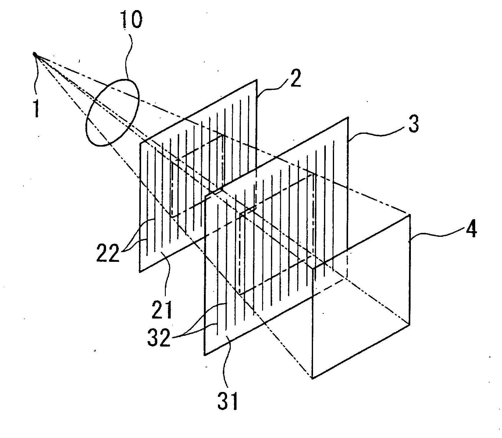
[0064] Spacing Z1 of the diffraction gratings 2 and 3 is taken to be 32 cm for the Talbot effect to appear due to the diffraction grating 2. A plastic sphere approximately 1 mm in diameter is used as the test subject 10.
[0065] The test subject 10 is positioned between the X-ray source 1 and the first diffraction grating 2 directly in front of the first diffraction grating 2.
[0066] In this state, X-rays irradiated from the X-ray source are detected by the X-ray image detector arranged directly behind the diffracti...
experimental example 3
[0072] Here, an experimental example of tomography is shown using the apparatus of this embodiment.
Experimental Conditions
[0073] The experimental conditions of experimental example 3 are the same as for experimental example 2.
[0074] The tomography employing this embodiment requires the following three procedures. Procedure 1 transforms from an X-ray image (hereinafter referred to as a “Moire fringe image”) detected by the X-ray image detector 4 to “a distributed image of an angle where X-rays are curved by diffraction effects due to the test subject 10” (hereafter referred to as a “phase shift differential image”). Procedure 2 acquires an image (hereinafter referred to as a “phase shift image”) expressing shifts in phase by integrating the phase shift differential image. Procedure 3 recreates a three-dimensional image using tomography using a phase shift image acquired using a plurality of photographing directions.
[0075] Procedure 1 employs stripe scanning techniques. In this me...
PUM
| Property | Measurement | Unit |
|---|---|---|
| distance | aaaaa | aaaaa |
| distance | aaaaa | aaaaa |
| distance | aaaaa | aaaaa |
Abstract
Description
Claims
Application Information
 - R&D
- Intellectual Property
- Life Sciences
- Materials
- Tech Scout
- Unparalleled Data Quality
- Higher Quality Content
- 60% Fewer Hallucinations
Browse by: Latest US Patents, China's latest patents, Technical Efficacy Thesaurus, Application Domain, Technology Topic, Popular Technical Reports.
© 2025 PatSnap. All rights reserved.Legal|Privacy policy|Modern Slavery Act Transparency Statement|Sitemap|About US| Contact US: help@patsnap.com


