Molding machine and locking mechanism for securing tie bars

a technology of locking mechanism and clamping machine, which is applied in the field of rotating clamping mechanism, can solve the problems of requiring a drive mechanism equally robust, requiring considerable energy, and requiring physical sizeable and relatively costly drive mechanisms, so as to achieve simple clamping assembly, reduce energy consumption, and ensure the effect of sealing

Inactive Publication Date: 2005-12-29
HUSKY INJECTION MOLDING SYST LTD
View PDF9 Cites 23 Cited by
  • Summary
  • Abstract
  • Description
  • Claims
  • Application Information

AI Technical Summary

Benefits of technology

[0015] In still yet another aspect of the present invention there is provided a method of effecting clamping of a tie bar or column in an injection molding machine having fixed thereto at least one two-piece clamp piston assembly through which the tie-bar or column extends, the two-piece clamp piston assembly comprising: a body portion having a channel extending through the body portion, the channel dimensioned to surround the tie bar or column and further including an inner surface into which are mounted a first set of contacts pads and a cylindrical clamp bushing insert having an external surface into which are mounted a second set of contact pads, the cylindrical clamp bushing locatable within the body portion whereby the first and second sets of contacts pads cooperate to produce at least two fluid sealable chambers within the two-piece clamp piston assembly; the method comprising: independently and freely of the body portion of the clamp piston assembly, causing independent rotation of the clamp bushing insert through the controlled and selective fluid pressurization of the sealable chambers, whereby volumes of the respective fluid sealable chambers vary with time and the clamp bushing insert selectively achieves positive engagement with the tie bar or column.
[0016] Advantageously, the present invention provides a simplified clamping assembly that is actuated by a drive that consumes lower energy. More particularly, the present invention removes the need to spin the entire piston. Additionally, with the reduced mass that is now spun to engage the tie-bar, the present invention can be run faster and on a quieter basis. Furthermore, should there by any breakage or wear in the clamp piston assembly, in situ disassembly and replacement is generally simplified and repair costs potentially minimised to the replacement part, rather than a large assembly. Clearly, with the use of the present invention, the cost associated with providing an appropriately drive to cause positive engagement of the clamp bushing to the tie-bar is reduced, since the power developed by (and energy consumption of) that drive unit is reduced when compared with prior art systems.
[0017] The present invention further reduces the amount of hydraulic shock that otherwise occurs with systems that rotate the entire clamp piston assembly. Moreover, the present invention reduces noise associated with high pressure rise rates in the cylinder and further reduces ancillary component loading.

Problems solved by technology

In the injection molding of large articles, such as in the molding of car body parts and the like, the injection molding machines also develop considerable closure tonnage.
In relation to the periodic rotation of the entire clamp piston, the moment of inertia and, fundamentally, the weight of the clamp piston assembly requires equally robust, physically sizeable and relatively costly drive mechanisms.
Consequently, considerable energy is expended in rotating the entire clamp piston, which energy consumption has an impact on manufacturing cost overheads.
Moreover, from a manufacturing perspective, the cost for producing a unitary clamp piston is not inexpensive, especially when one considers the inherent complexity and highly-toleranced nature of a relatively large component.
Also, in the event of any wear or malfunction in the teeth in the clamp piston, the entire clamp piston assembly has to be replaced, which is both expensive and time consuming.
With the high pressure rise rates in these cylinders, such prior art systems are susceptible to high amounts of hydraulic shock.
Furthermore, there is an associated high level of noise and a high loading of individual components.
Whilst this configuration mitigates the requirement to rotate the clamp piston itself, the complexity and reliability of the drive mechanism offsets any potential advantage (particularly fiscal benefit) that is obtained from having a lower power-rated (and hence cheaper) rotational drive mechanism.
Moreover, should anything malfunction, then a qualified engineer would expend considerable time in disassembling the combined clamp piston and drive assemblies; and such an extended down-time would be unacceptable in a production environment essentially seeking 24 / 7 operation.

Method used


Image

  • Molding machine and locking mechanism for securing tie bars
  • Molding machine and locking mechanism for securing tie bars
  • Molding machine and locking mechanism for securing tie bars

Examples


Embodiment Construction

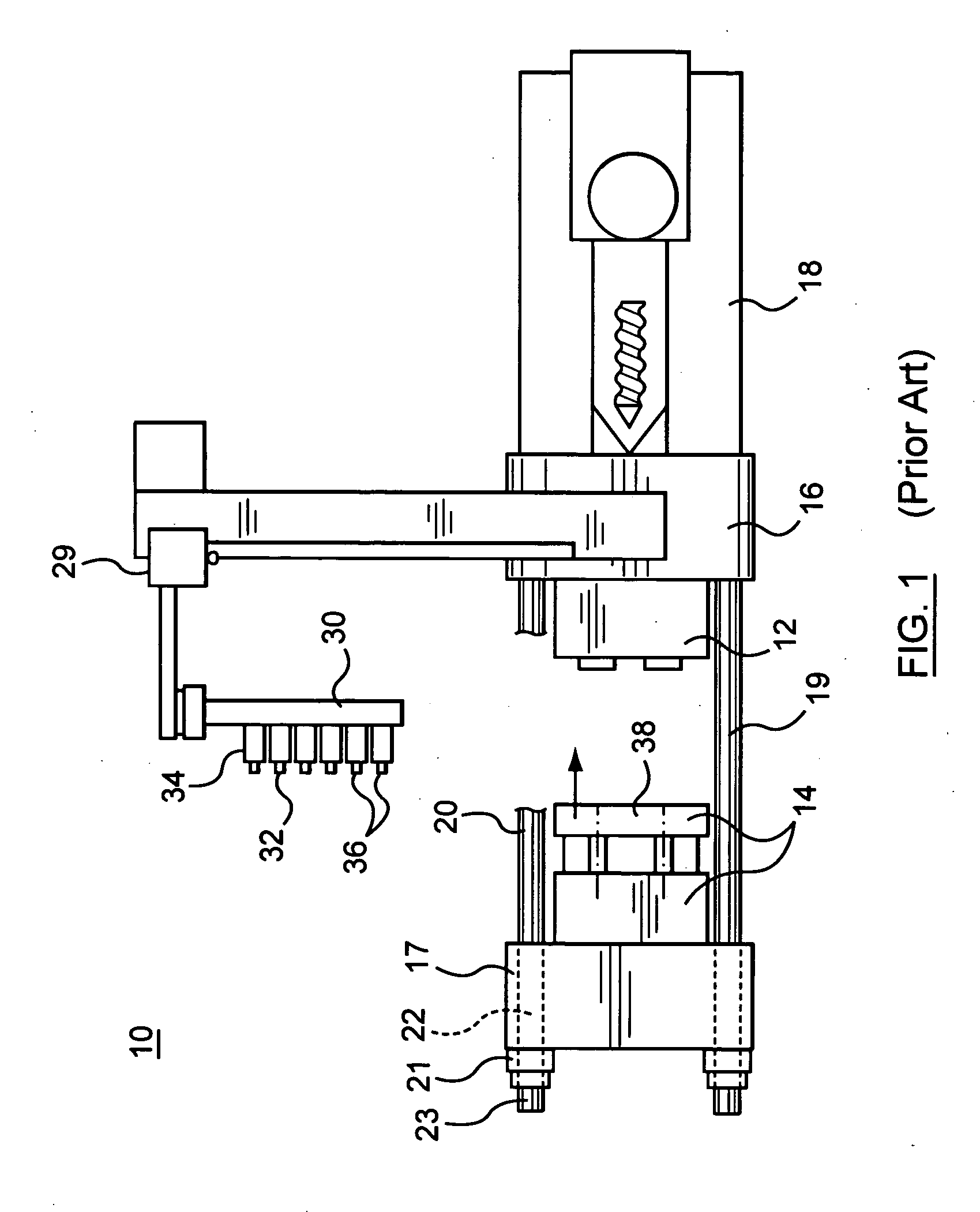
[0023]FIG. 1 shows a typical injection molding machine 10 that can be adaptable to support the rotatable clamping (or locking) mechanism of the present invention. During each injection cycle, the molding machine 10 produces a number of plastic parts corresponding to a mold cavity or cavities defined by complementary mold halves 12, 14 located within the machine 10.

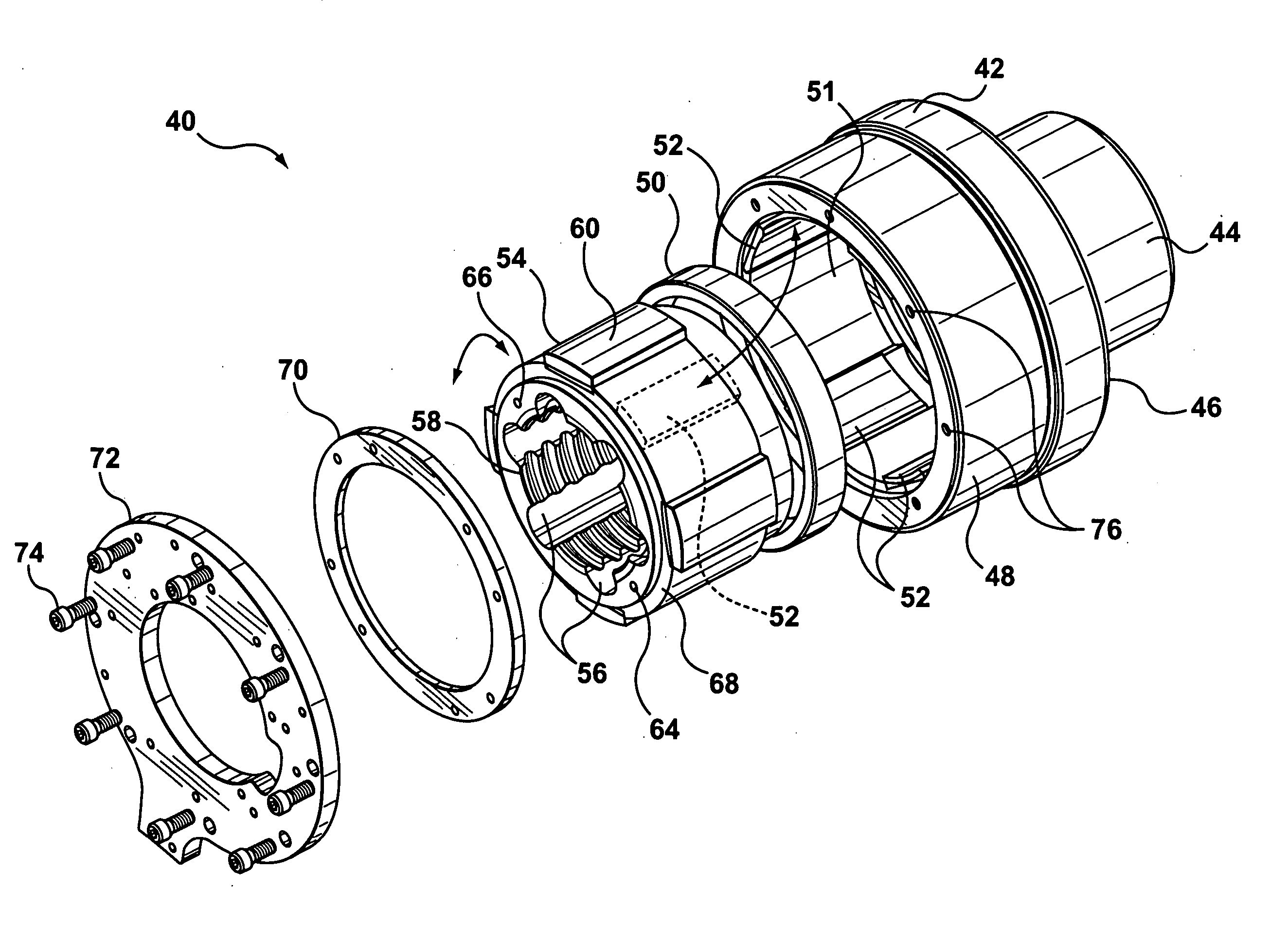
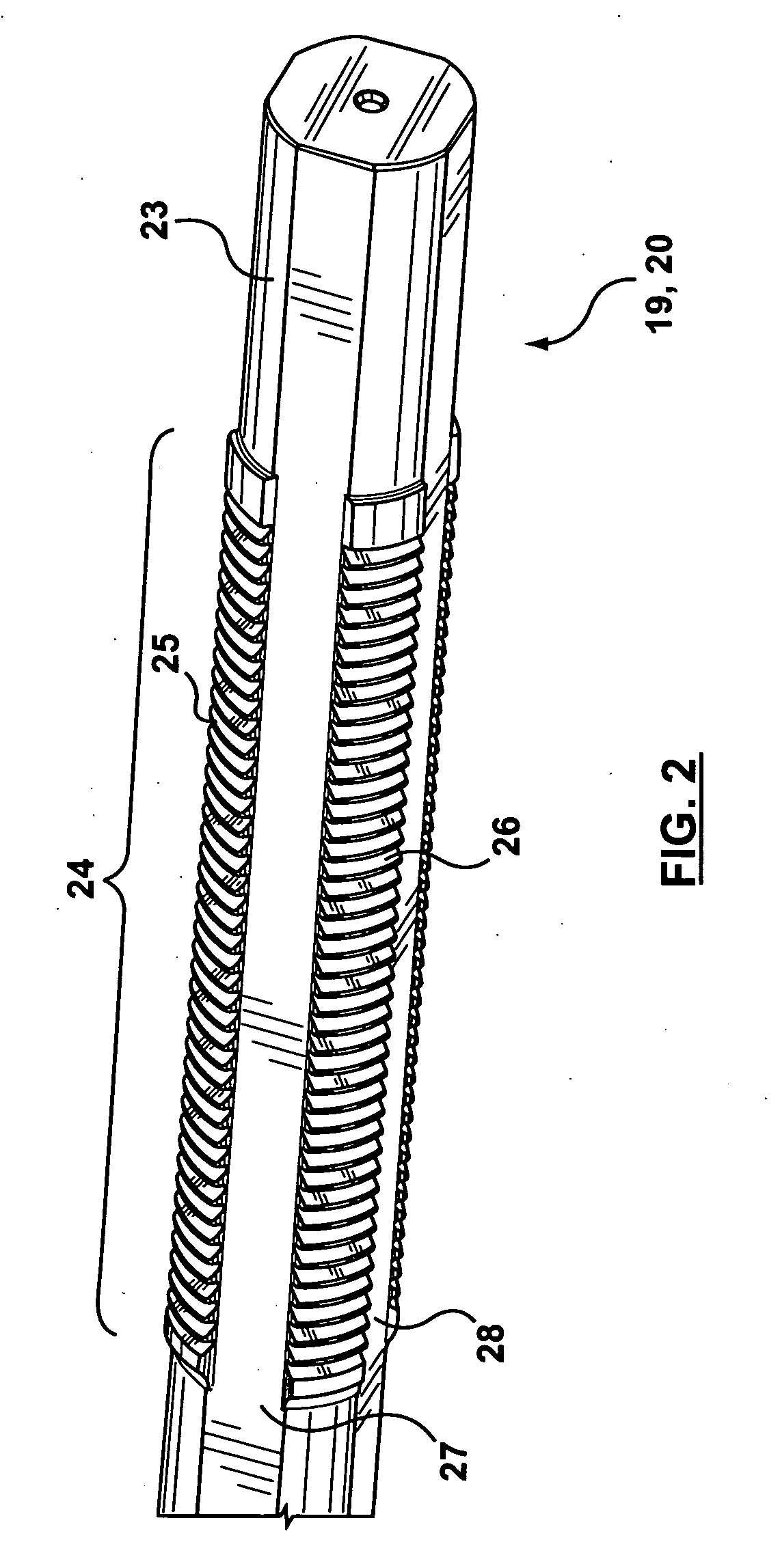
[0024] The injection-molding machine 10 includes, without specific limitation, molding structure, such as a fixed platen 16 and a movable platen 17 as well as an injection unit 18 for plasticizing and injecting material. In operation, the movable platen 17 is moved relative to the fixed platen 16 by means of stroke cylinders (not shown) or the like. Clamp force is developed in the machine, as will readily be appreciated, through the use of tie bars 19, 20 and a tie-bar clamping mechanism 21. The clamping mechanism 21 is (generally) fixedly attached to the moving platen 17 (typically through the use of bolts), with each cl...


PUM

PropertyMeasurementUnit
weightaaaaaaaaaa
volumesaaaaaaaaaa
circumferenceaaaaaaaaaa

Abstract

FIG. 3 illustrates a clamp piston assembly (40) comprising a body portion (44, 46, 48) in which a pocket is provided. The pocket is arranged to receive an insert in the form of a rotatable clamp bushing (48). Sets of blades or wear pads (52, 62) are positioned on both an internal surface (51) of the pocket and the external surface of the clamp bushing (48) and cooperate to form sealable chambers that extend about the circumference of the clamp bushing (48). These chambers are in fluid communication with suitable processor-controlled valves (82, 84) and hydraulic or pneumatic pumps (80) that operative to purge and inject fluid from and into the chambers. Pressurized fluid acting within selected chambers causes rotation of the clamp bushing (54). The insert also contains a row of teeth (58) arranged to selectively engage corresponding teeth (25, 26) in a tie-bar (19, 20). The clamp bushing (48) is hence independently rotatable from its surrounding body (48) that, in use, is mechanically attached to an injection molding machine (10).

Description

FIELD OF THE INVENTION [0001] This invention relates, in general, to a rotatable clamping (or locking) mechanism that complementarily acts in association with a press (or the like) to develop, ultimately, a clamp force or closure tonnage. The present invention is more particularly, but not exclusively, applicable to the configuration of a clamp piston assembly that is used to securely clamp up, during a molding process and particularly an injection molding process, a column or tie-bar to a platen to produce a closed force path. SUMMARY OF THE PRIOR ART [0002] From the exemplary perspective of an injection molding environment, system designers are faced with having to provide reliable and robust clamping systems that operate for extended periods with minimum, if any, maintenance. More particularly, clamp units and clamp assemblies in injection molding systems are designed to run on an almost continuous basis for weeks at a time, if not months at a time. Typically, machine cycle times...

Claims


Application Information

Patent Timeline
Patent Type & Authority Applications(United States)
IPC IPC(8): B29C45/66B29C45/67
CPCB29C2045/6735B29C45/6728
Inventor LOOIJE, PETER ADRIAN
Owner HUSKY INJECTION MOLDING SYST LTD
Why Eureka
Try Eureka