Method for measuring the speed of an electrical machine

a technology of electrical machines and speed measurements, applied in the direction of digital computer details, electric controllers, instruments, etc., can solve the problems of unfavorable, measured speed values (k), and outside the tolerance band

Inactive Publication Date: 2006-01-05
SCHAEFFLER TECH AG & CO KG
View PDF5 Cites 5 Cited by
  • Summary
  • Abstract
  • Description
  • Claims
  • Application Information

AI Technical Summary

Benefits of technology

[0006] An object of the present invention is to provide a method for measuring the speed of an electrical machine that will enable a relatively precise speed-measurement signal, which exhibits little time delay with respect to the measured speed values, to be determined in a simple manner.

Problems solved by technology

Thus, measured speed values ω(k), which lie outside of the tolerance band and, therefore, are not plausible, are advantageously limited to the tolerance band, the limit values for the tolerance band being dynamically determined.

Method used


Image

  • Method for measuring the speed of an electrical machine
  • Method for measuring the speed of an electrical machine
  • Method for measuring the speed of an electrical machine

Examples


Embodiment Construction

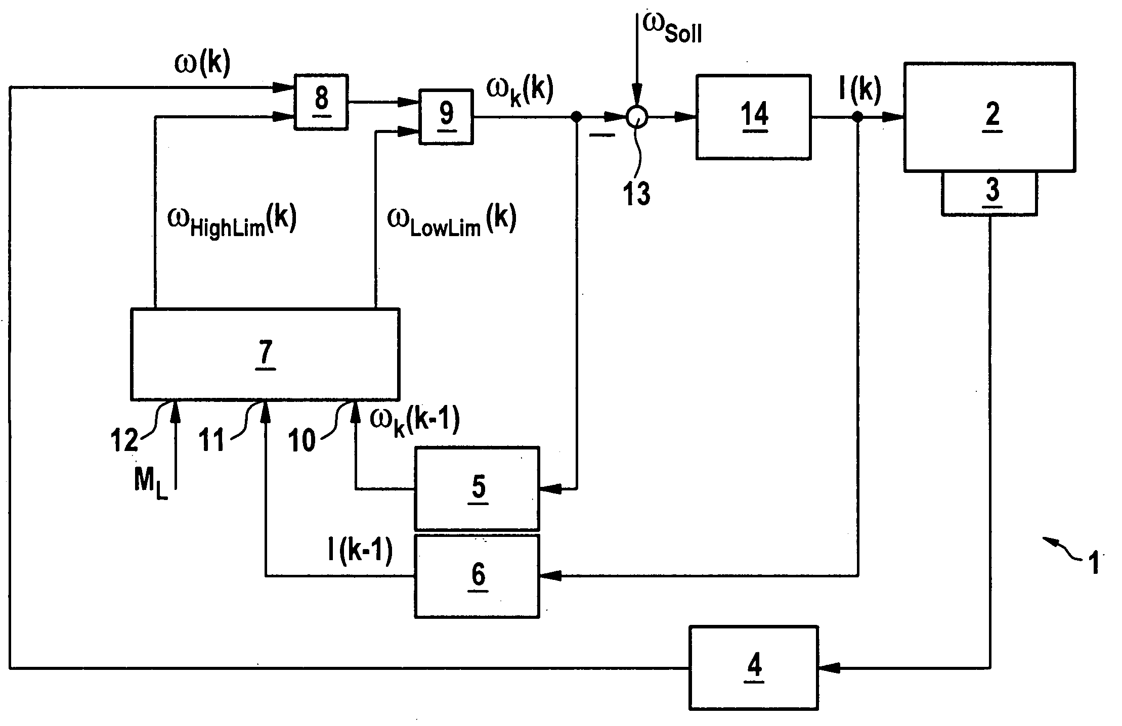
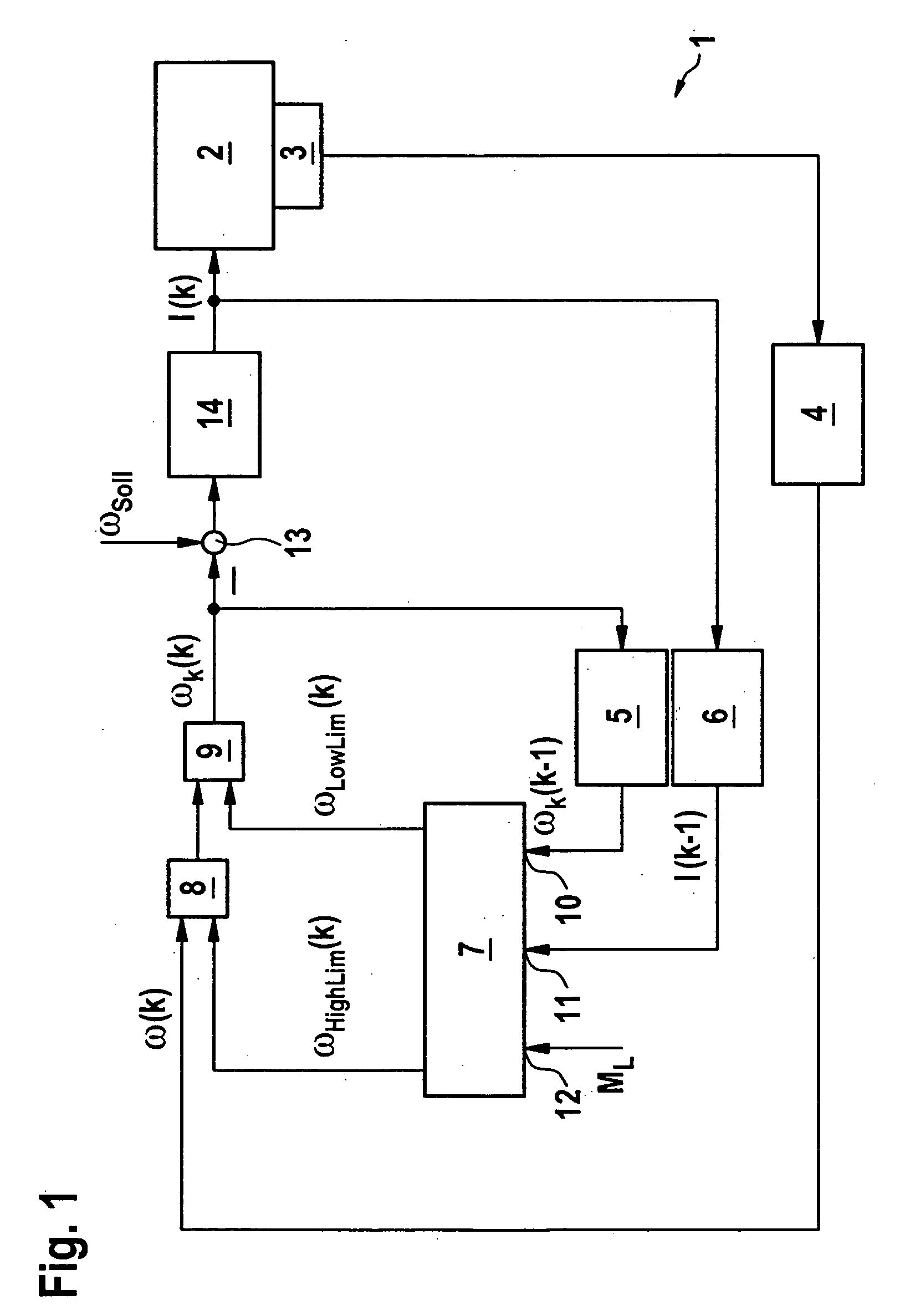
[0018] An electrical device has an electronically commutated motor and a speed control circuit, denoted as a whole by 1, for the electronically commutated motor. The electronically commutated motor is used as a drive motor for an adjusting device of a motor vehicle, for example for a camshaft-angle control device of a reciprocating piston combustion engine or for an adjusting device for a shift finger of a parallel manual transmission. The electronically commutated motor and the mechanical load driven by it form a controlled system which is denoted by 2 in the drawing.

[0019] Mounted on the electronically commutated motor is a speed sensor 3, which, for each phase of the electronically commutated motor winding, has a Hall-effect sensor, which cooperates in a generally known manner with a magnetized ring of the rotor of the electronically commutated motor in order to sample a speed-measurement signal for the rotor speed. The speed-measurement signal is fed to a sample and hold elemen...


PUM


Abstract

In a method for measuring the speed of an electrical machine having a stator, a rotor and a winding, in particular of an electronically commutated motor, a speed-measurement signal ω is sampled, in that a measured speed value ω(k) for the rotor is determined for each of a series of sampling instants. Moreover, a moment of inertia value for the mass moment of inertia of the rotor is determined. In addition, a current signal I is sampled, in that a current value I(k) for the electrical current in the winding is determined for each of the sampling instants. An estimated value ωs(k) for each of the measured speed values ω(k) is determined from a measured speed value ωk(k−1) assigned to an earlier sampling instant, from the current signal I and from the moment of inertia value. A tolerance band containing the estimated value ωs(k) is assigned to this estimated value ωs(k). If the measured speed value ω(k) lies outside of the tolerance band, the measured speed value ω(k) is replaced by a speed value ωk(k) that is within the tolerance band.

Description

[0001] Priority is claimed to German Patent Application No. DE 10 2004 032 264.3, filed on Jul. 3, 2004, the entire disclosure of which is incorporated by reference herein. BACKGROUND [0002] The present invention is directed to a method for measuring the speed of an electrical machine having a stator, a rotor and a winding, in particular of an electronically commutated motor, a speed-measurement signal ω being sampled, in that a measured speed value ω(k) for the rotor is determined for each of a series of sampling instants. [0003] A method of this kind for measuring the speed of an electronically commutated motor having a permanent magnet rotor, on whose periphery magnetic segments are arranged, which cooperate with an electronically commutated winding disposed on the stator, is known in the field. In this context, Hall-effect sensors mounted on the stator of the electronically commutated motor are used to record the position of the magnetic segments. Depending on the magnetic field...

Claims


Application Information

Patent Timeline
Patent Type & Authority Applications(United States)
IPC IPC(8): H02P5/00
CPCH02P23/03H02P23/14H02P23/12G05B11/06H02P21/00
Inventor STORK, HOLGERZIMMERMANN, MARTINSCHUHEN, MICHAEL
Owner SCHAEFFLER TECH AG & CO KG
Why Eureka
Try Eureka