Laboratory animal housing with euthanizing function

a technology of cage racks and laboratory animals, which is applied in the field of laboratory animal housing cage rack systems, can solve the problems of unsuitability of animals that may have lived through a given experiment, leakage of ventilation air, and flow of leakage air, and achieve the effect of increasing the concentration of co2 gas

Inactive Publication Date: 2006-01-19
THOREN CAGING SYST +1
View PDF21 Cites 73 Cited by
  • Summary
  • Abstract
  • Description
  • Claims
  • Application Information

AI Technical Summary

Benefits of technology

[0020] The animal cages preferably are air impermeable boxes suspended from hollow shelves that define internal conduits for supply and exhaust of air, coupled to the supply and exhaust conduits. When initiating a euthanizing cycle, the supply air is discontinued and a gas, preferably CO2 is supplied while continuing to operate the exhaust system for a defined period of time. This insulates the system, i.e., increases the concentration of CO2 gas in the cages, first anesthetizing the animals and eventually displacing oxygen to a lethal concentration of gas. After a user defined timed interval, the CO2 gas supply preferably is shut off, and the exhaust system is stopped for a further timed “soak” interval. The cessation of ventilation currents permits the CO2 gas, which is heavier than air, to settle without turbulence in the cages, displacing any oxygen and further increasing the CO2 gas concentration while removing oxygen, in the areas occupied by the animals. After a soak interval timed so that all the affected animals have expired, the inlet is recoupled to ventilation air system, the CO2 gas supply remains shut off and the exhaust is operated to permit the cages to be vented. The cages and animals can be removed safely.

Problems solved by technology

A lid or sealing filter cover between the cage box and shelf can help to seal the ventilation paths, but there is typically some leakage of ventilation air.
The result is some flow of leakage air, either outwardly from the cages into the surrounding air, or inwardly from the surrounding air into the cages.
Animals that may have lived through a given experiment are often unsuitable as subjects in a later experiment due to potential influence from the former experiment.
Continued maintenance of such animals cannot be justified.
However, the technique may be stressful to the animals.
The CO2 gas technique also can be labor intensive, particularly where a large number of animals are to be euthanized.
Dry ice is very cold and its use as a supply of CO2 gas is considered likely to traumatize the animals.
Use of dry ice for euthanasia is generally considered an unacceptable practice.
Nevertheless, there is stress for the animals and work for the technician.
Although the animals might be processed in their individual home cage boxes, there is stress in removing the cage boxes from their normal location, sealing the gas fitting lid to each individual cage box in turn and proceeding with the timed process.
Processing one box at a time is time consuming and inefficient for the operator, who is inclined to combine unfamiliar animals into one cage box for processing.
Combining unfamiliar animals in a cage is stressful for the animals.
One might extend Anderson to combining a number of cage boxes in some sort of sealed vault for application of the process, which would also be stressful for the animals and inefficient for the operator.
However, this advantage is achieved with substantial inconvenience for the operators, who are to disassemble the air supply and air plenum structures for each cage rack to be processed, modify the cage rack by installing a CO2 gas emission apparatus, operate the CO2 gas supply with sufficient pressure, flow and timing controlled manually, and finally to remove these arrangements afterwards.
It would be most inefficient to build all cage ventilation apparatus with a euthanasia capability, as well as expensive and prone to accidents, simply to avoid the need to stress the animals by relocating them if and when euthanasia became necessary.

Method used


Image

  • Laboratory animal housing with euthanizing function
  • Laboratory animal housing with euthanizing function
  • Laboratory animal housing with euthanizing function

Examples


Embodiment Construction

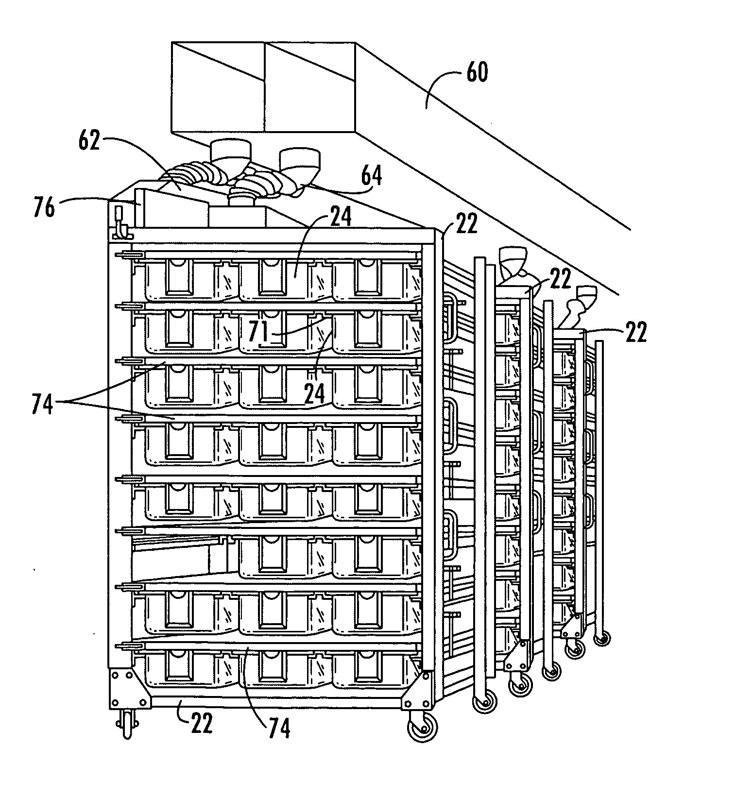
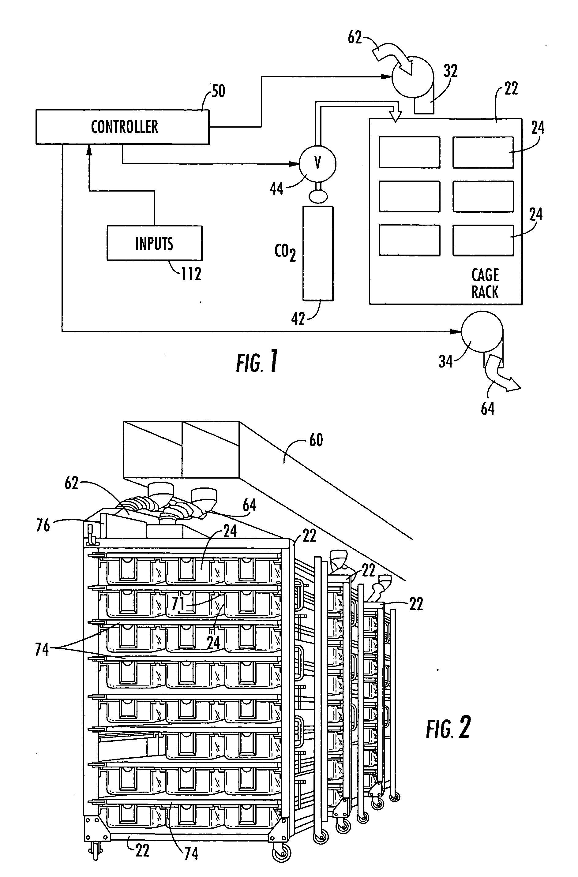
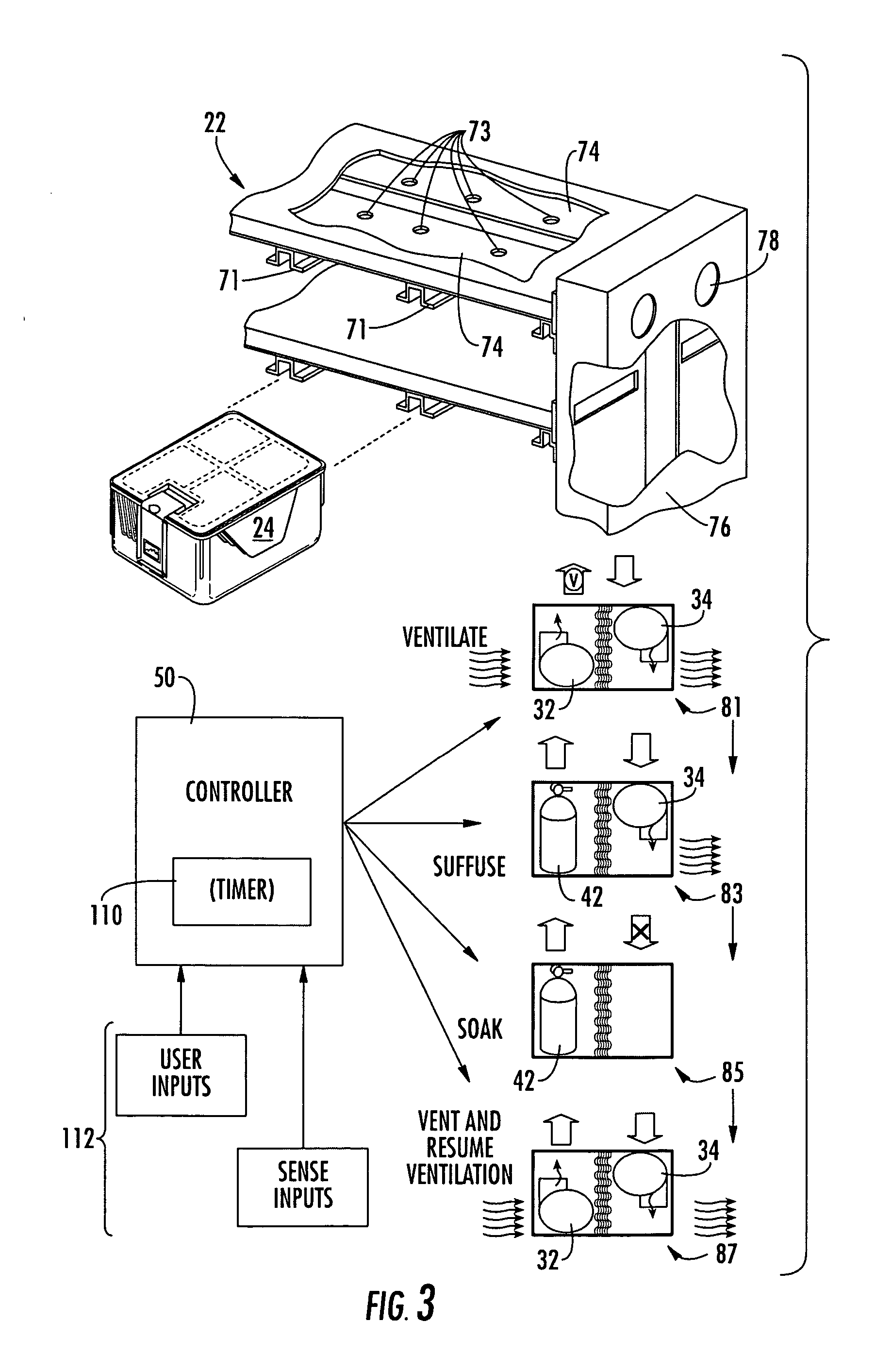
[0029] Carbon dioxide (CO2) overdose is a known euthanasia technique and has been employed for mice as discussed in the background information above. Known techniques, for example as in U.S. Pat. No. 4,941,431—Anderson, process animals in air impervious cage boxes under a sealing cover containing gas fittings by which oxygen-displacing gas is injected into the cage box. Such a process of treating animals in units of cage boxes require that animals be moved into a cage box, or even if not move, that that cage boxes be removed individually from their normal environment as part of the process.

[0030] It may be stressful for animals to be displaced from their normal conditions. If moved into the same cage box the animals may become separated from their familiar cohabitant animals and mingled with strange animals. Moving the animals and / or processing cage boxes individually can be labor intensive and time consuming. The associated stress can excite the animals and complicate the procedur...


PUM


Abstract

A high density animal housing system with an air source conduit and an air exhaust conduit is normally coupled to one or more ventilating animal cage racks through standard inlet / outlet fittings. A euthanasia fixture is coupled into the standard inlet / outlet fittings and selectively and sequentially operates valves and / or blowers to switch from supply of respiration air to a gas supply, to open and close the flow to the exhaust and to resume ventilation afterwards, for venting. The sequence is timed and controlled by a programmable controller that activates the associated blowers and valves automatically to follow a user selected sequence. The system anesthetizes and then euthanizes the animals via the same flow conduits that otherwise supply respiration air, requiring no rack modifications and little if any human attention other than to couple the rack to the ventilation system at the euthanasia fixture. Operator inputs allow selection among sequences. Status sensing inputs prevent initiation or continuation of a cycle in the event of certain faults.

Description

BACKGROUND OF THE INVENTION [0001] 1. Field of the Invention [0002] The invention relates to the field of laboratory animal handling, providing an animal housing cage rack system with a euthanizing capability. The animals in all or part of a cage rack of the type that normally houses the animals can be asphyxiated by automatic staged displacement of cage air with CO2 gas. In this way the animals are euthanized with minimal associated stress and without danger to human operators. [0003] 2. Prior Art [0004] High density animal housing facilities are known, for example, from U.S. Pat. Nos. 5,044,316; 4,690,100; 4,402,280; and 4,343,261, wherein small animals such as mice, rats, rabbits or the like are housed in molded plastic cage boxes that are supported on hollow shelves with integral air supply and air exhaust ducts. The cage boxes are supported on flanges under the shelves. Openings in the underside of the shelves allow the supply and exhaust ventilation air lines to be coupled thr...

Claims


Application Information

Patent Timeline
Patent Type & Authority Applications(United States)
IPC IPC(8): A01K1/03
CPCA01K1/031A22B3/005A22B3/00
Inventor DRUMMOND, ROBERT A.LIPMAN, NEIL S.
Owner THOREN CAGING SYST
Why Eureka
Try Eureka