
Dental light devices having an improved heat sink

a technology of heat sink and dental light, which is applied in dentistry, spanners, wrenches, etc., can solve the problems of increasing the weight of hand-held curing lights, affecting the operation efficiency of curing lights, so as to achieve efficient removal or discharging heat

Active Publication Date: 2006-01-19
DISCUS DENTAL LLC
View PDF84 Cites 18 Cited by
  • Summary
  • Abstract
  • Description
  • Claims
  • Application Information

AI Technical Summary

Benefits of technology

[0010] The present invention relates to a heat sink material that can more efficiently remove or divert heat from a light source or sources with a given weight of heat sink material when compare to a heat sink made of a solid block of thermally conductive material such as metal.
[0011] The present invention further relates to a heat sink that can more efficiently remove or divert heat from a curing light device when a reduced weight of heat sink material is used.
[0012] The present invention includes a heat sink having at least one suitable phase change material including organic materials, inorganic materials and combinations thereof. These materials can undergo substantially reversible phase changes, and can typically go through a large, if not an infinite number of cycles without losing their effectiveness.

Problems solved by technology

Heat generated by any curing lights during operation can be problematic.
This same kind of problem is also encountered in photobleaching lights.
Blocks of metal can be efficient, but they can also add significant weight to any hand held curing light.
The added weight can in turn contribute to increased fatigue of the dental professional using the curing light.
When a fan is also used in the same curing light, it adds additional weight, can be noisy and can contribute to reduced battery life and reliability of the device.
The noise also adds to the anxiety of the patients who are often reluctant and fearful of dental procedures.

Method used


Image

  • Dental light devices having an improved heat sink
  • Dental light devices having an improved heat sink
  • Dental light devices having an improved heat sink

Examples


example

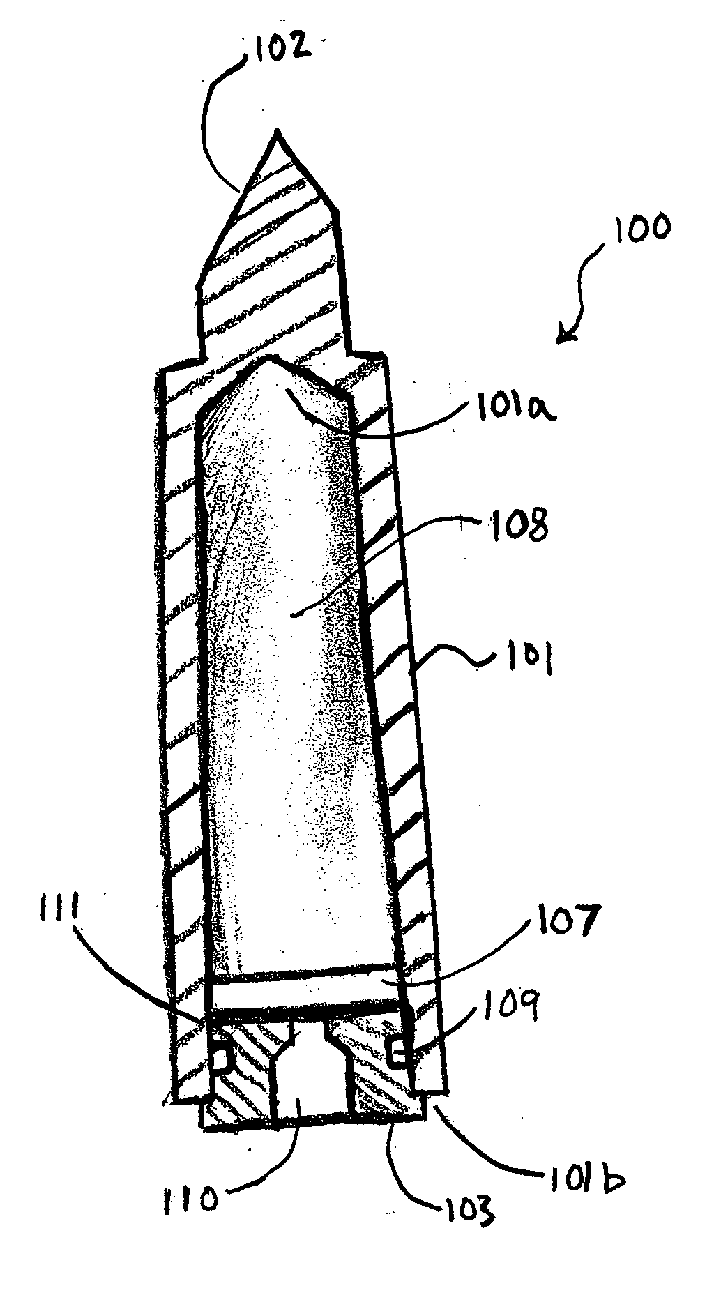
[0100] A heat sink embedded in a dental curing light was constructed as follows:

[0101] Composition and property of phase change material used:

[0102] Phase change material (PCM): Sodium Hydrogen Phosphate Dodecahydrate (Na2HP4.12H2O) having the following properties was used:

[0103] Melting Point: 36° C.

[0104] Heat of Fusion: 280 kj / kg

[0105] Specific Heat: 1.94 kJ / kg° C. (solid), 1.60 kJ / kg° C. (liquid)

[0106] Density: 1520 kg / m3 (solid), 1450 kg / m3 (liquid)

[0107] Thermal Conductivity: 0.514 W / m° C. (solid), 0.476 W / m° C. liquid)

[0108] The thermally conductive housing: a copper casing (tellurium copper 145), having wall thickness of about 1.5 mm.

Preparation:

[0109] The phase change material was heated for 45 minutes at 55° C. in an oven until melted. 1.2 mL of phase change material in liquid phase was loaded into the hollow copper casing of the heat sink using a syringe. The heat sink was cooled with a fan for 30 minutes before a cap was pressed into place to seal the chamber....


PUM


Abstract

The present invention relates to a heat sink material that can more efficiently remove or divert heat from a light source or sources with a given weight of heat sink material when compare to a heat sink made of a solid block of thermally conductive material such as metal. It further relates to a heat sink that can more efficiently remove or divert heat from a curing light device when a reduced weight of heat sink material is used. The inventive heat sink has at least one suitable phase change material including organic materials, inorganic materials and combinations thereof. These materials can undergo substantially reversible phase changes, and can typically go through a large, if not an infinite number of cycles without losing their effectiveness.

Description

CROSS-REFERENCE TO RELATED APPLICATIONS [0001] This application claims the benefit of U.S. provisional application Ser. Nos. 60 / 585,224, filed Jul. 2, 2004, entitled “Dental Light Devices With Phase Change Heat Sink”; 60 / 658,517, filed Mar. 3, 2005, entitled “Apparatus and Method For Radiation Spectrum Shifting in Dentistry Application”; 60 / 641,469, filed Jan. 4, 2005, entitled “Lamp For Dentistry Applications”; 60 / 647,580, filed Jan. 26, 2005, entitled “Light Guide For Dental Whitening Lamp”; 60 / 641,468, filed Jan. 4, 2005, entitled “Light Guide For A Dental Whitening Lamp”; 60 / 647,612, filed Jan. 26, 2005, entitled “Light Path Apparatus For A Dental Lamp”; 60 / 604,577, filed Aug. 25, 2004, entitled “Lip Retractors”; 60 / 594,297, filed Mar. 25, 2005, entitled “Curing Light Having A Detachable Tip”; 60 / 631,267, filed Nov. 26, 2004, entitled “Curing Light Having A Reflector”; 60 / 594,327, filed on Mar. 30, 2005, entitled, “Curing Light”; and 60 / 664,696, filed Mar. 22, 2005, entitled “Cu...

Claims


Application Information

Patent Timeline
IPC IPC(8): A61B1/06A61K6/884
CPCA61C19/004F28D2021/0029F28D20/02A61K8/19A61K8/20A61K8/21A61K8/24A61Q11/00A61K6/864A61K6/884C08L91/06
Inventor HAYMAN, ROBERTSHABANY, YOUNESROSE, ERIC P.
Owner DISCUS DENTAL LLC
Learn More