
Dual power bus for battery powered device

a battery-powered device and dual-power bus technology, applied in the direction of electric variable regulation, process and machine control, instruments, etc., can solve the problems of inability to work properly, take several minutes or longer, and undesirable behaviour of consumers, so as to improve the effective battery life, reduce the voltage drop of the battery, and improve the effect of battery li

Inactive Publication Date: 2006-01-26
WOLFSON MICROELECTRONICS LTD
View PDF6 Cites 20 Cited by
  • Summary
  • Abstract
  • Description
  • Claims
  • Application Information

AI Technical Summary

Benefits of technology

"The present invention provides a power supply circuit for a battery-powered device that has a common load regulator for two different power sources. The load regulator has two input devices, one connected to each power source, and the regulator is able to switch between the two power sources based on the needs of the device. This allows for optimal performance and cost-effectiveness. The circuit also includes a charging circuit for the battery, which can be connected to either the battery or an external power source. The use of a common regulator and MOS-based transistors can reduce the size and power consumption of the circuit. The technical effects of this invention include improved battery life, reduced size and power consumption of the circuit, and improved stability of the linear regulators."

Problems solved by technology

One problem with this type of scheme relates to the time which the system takes to become active when powered from the bus (11) or alternate (13) supply with a discharged battery 10.
Thus the system supplied by the load regulators 15 will not work properly until the battery 10 is charged up.
Where the battery is heavily discharged, this might take several minutes or longer.
This behaviour is undesirable to consumers who now desire “instant-on” behaviour.
A further problem is that the charger current control 14 or 14′ limits the current to the node Vbat, to avoid too rapid charging of the battery 10.
Thus if they take 99 mA, only 1 mA is available to charge the battery, further increasing the time required for the system to operate properly.
Even if the error is less gross than this, and say there is only a 25% reduction in charger current actually reaching the battery, this may well confuse the analog or digital control of the battery charging process, affecting the effective Icharge-Vbat trajectory, and causing a charging time that is still sub-optimum, even allowing for the 25% reduction in battery charging current.
This is not just extending charging time it is also decreasing the battery life time.
The circuit could be improved by sensing current flowing only into the battery 10, while controlling all current into Vbat, but this still does not guarantee adequate current into the other loads 15, as the splitting of current will be defined by the respective V-I characteristics of all circuits connected to the Vbat node, including the battery, so a discharged battery would tend to steal current away from loads expecting a higher voltage.
The main problem with this solution is the extra voltage drop between Vbat and Vsup when the load regulators 15 are driven from the battery 10 compared to the system of FIG. 1.
However the voltage drop across this additional switch device (Mc) effectively increases the minimum voltage required from the battery, and hence reduces the time the battery can provide this.
Lower on-resistance discrete MOS switches are more expensive as they require larger silicon area or more complex and specialized wafer processing.
More particularly, for systems where most of the circuitry of FIG. 1 or 3 is implemented on a single chip, the total area required for these switches has not only an impact on chip area and hence cost, but also may require so much area that the silicon die may not fit in the desired plastic package.
There is also a possible issue of problems arising from modulation of the voltage on Vsup caused by load variations on the load regulators 15.
This would also increase the complexity and hence cost of the circuit arrangement.
Also if Mc is regulated for example to deliver a Vsup at a fixed voltage difference below Vbat, this voltage difference will then have to be set to a worst-case voltage drop, which will make battery voltage headroom under non-maximum load conditions even worse.

Method used


Image

  • Dual power bus for battery powered device
  • Dual power bus for battery powered device
  • Dual power bus for battery powered device

Examples


Embodiment Construction

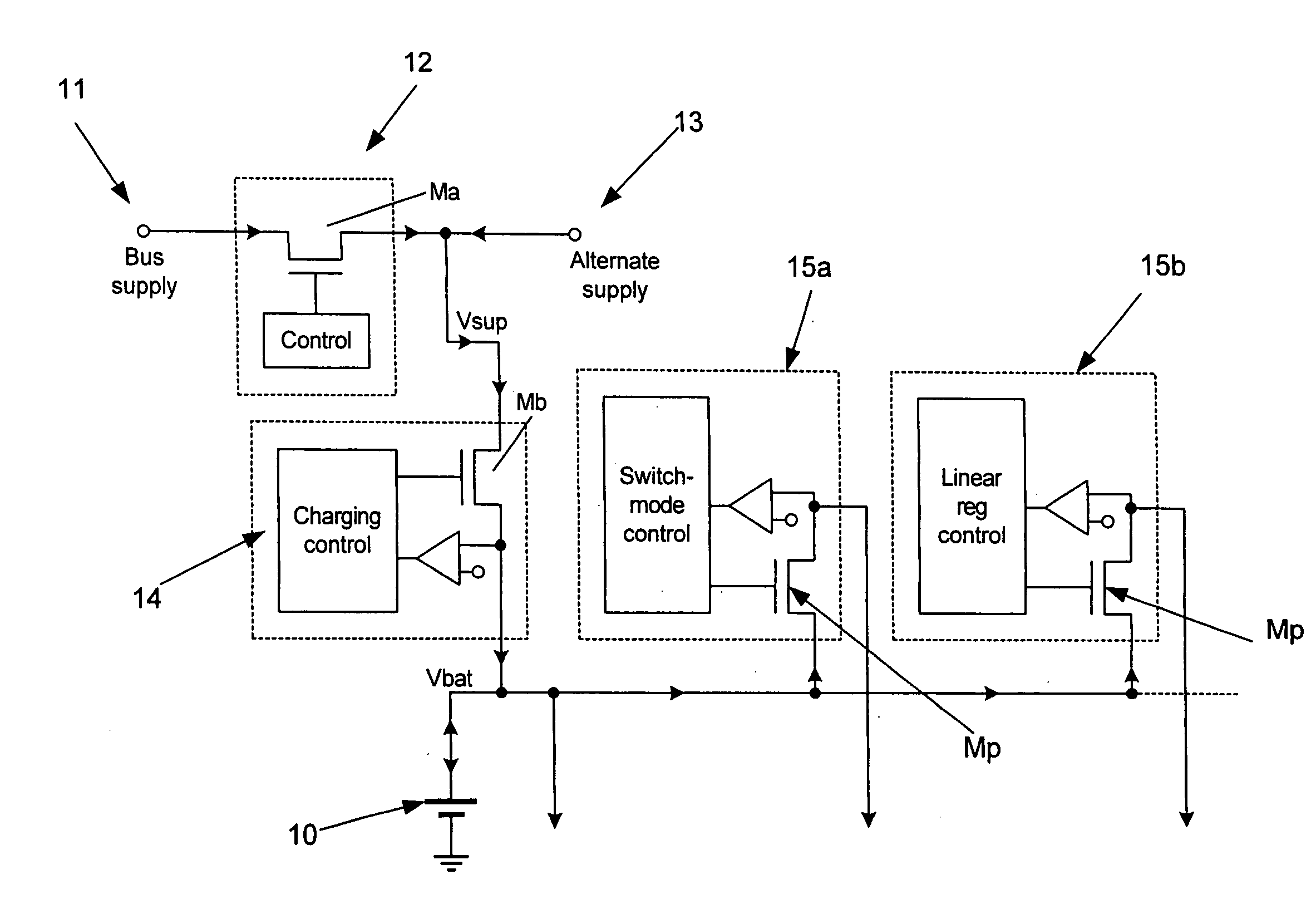
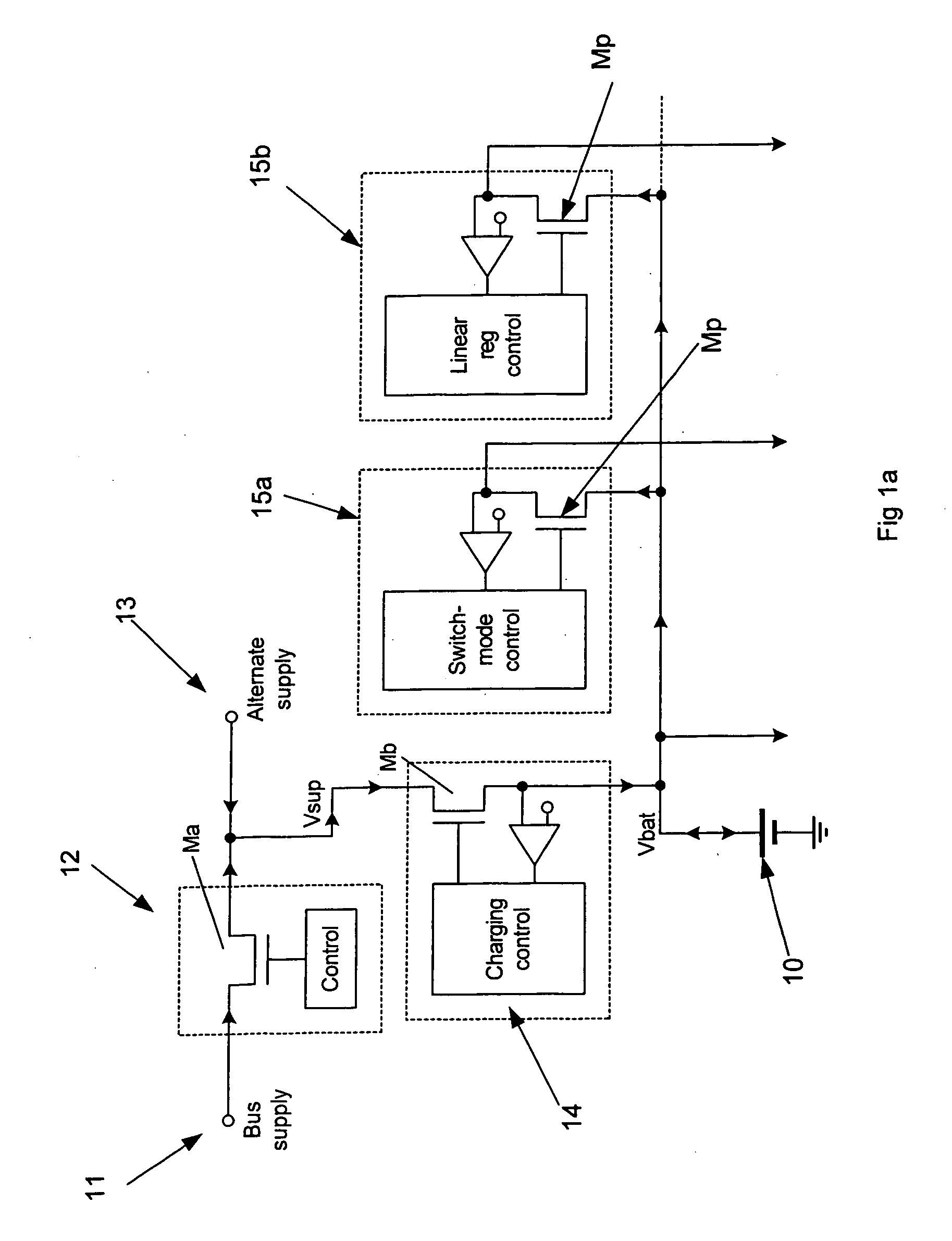
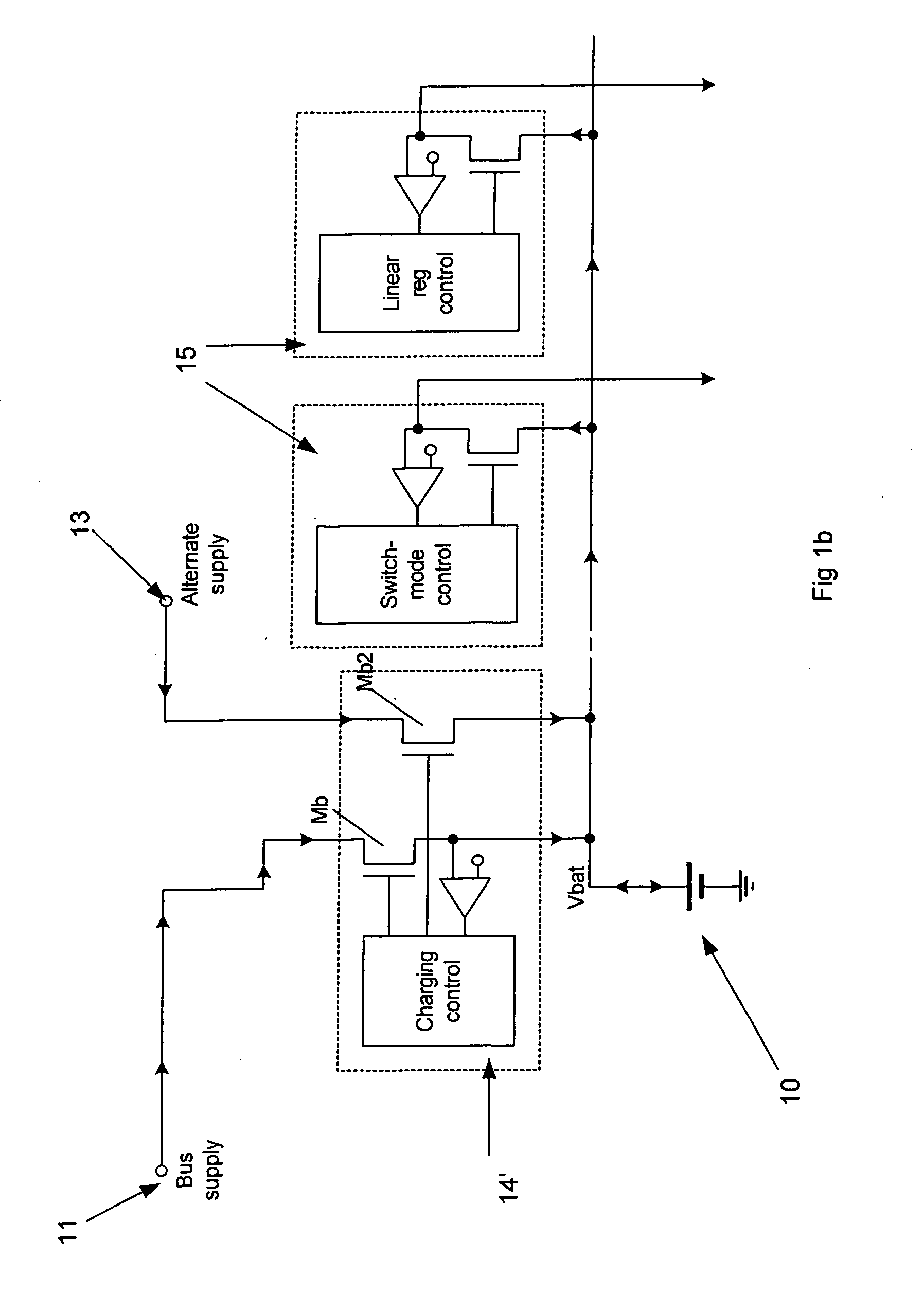
[0055]FIG. 4 shows a power supply circuit according to a first embodiment and comprises two non-battery power supplies, a bus supply 11 such as the power wires in a USB cable, and an external supply 13 such as a pre-regulated mains source. A bus regulator 12 conditions the bus supply 11, and this and the external supply 13 are connected at a common non-battery supply node Vsup which is coupled to a first power supply rail or bus PSR1. As with the systems of FIGS. 1 and 3, a battery charger circuit 14 is coupled between the non-battery common supply node Vsup and a re-chargeable battery 10. Other components in common with FIGS. 1 and 3 are referenced the same. The battery 10 of FIG. 4 is connected to a second power supply rail or bus PSR2 (also Vbat). Thus two power supply rails (PSR1 and PSR2) are provided for the load regulators 25.

[0056] The load regulators 25 each have two inputs, each with an associated pass device Mp1 and Mp2. One such input (Mp1) is connected directly to the ...


PUM


Abstract

The present invention relates to battery power peripheral devices such as MP3 players which are also periodically connected to another power source such as a mains wall socket or USB cable power bus. In particular, but not exclusively, the present invention relates to regulation of these voltage sources. In general terms the present invention provides a dual supply rail for the load regulators of a power supply circuit for a battery powered device. One supply rail is coupled to the battery, and the other is coupled to a non-battery source such as an external mains regulated source and / or a bus power wire from a USB cable or similar. The regulators have dual inputs, each for taking their input voltage from one of these supply rails.

Description

FIELD OF THE INVENTION [0001] The present invention relates to battery powered peripheral devices such as MP3 players or cell-phones which are also periodically connected to another power source such as a mains wall socket or USB cable power bus. In particular, but not exclusively, the present invention relates to regulation of these voltage sources. BACKGROUND OF THE INVENTION [0002]FIG. 1a shows a power supply system for a typical battery-powered peripheral device. The system comprises connections 11 and 13 to external power supplies, as well as to a re-chargeable battery 10. The external supplies are typically regulated (12) and / or switched to a common external supply node (Vsup) which supplies charging current to the battery through a charging circuit or controller 14. The battery 10 is coupled to an internal power bus which supplies one or more load regulators 15 which provide regulated voltage outputs to one or more parts of the peripheral device. For example one load regulato...

Claims


Application Information

Patent Timeline
Patent Type & Authority Applications(United States)
IPC IPC(8): G05F1/56H02J7/00H02J7/34
CPCH02J7/0068H02M1/10H02J7/34G05F1/59
Inventor FRITH, PETER J.SINAI, DAVID
Owner WOLFSON MICROELECTRONICS LTD
Learn More