Thermal barrier coatings with high fracture toughness underlayer for improved impact resistance

a thermal barrier coating and fracture toughness technology, applied in the direction of superimposed coating process, natural mineral layered products, instruments, etc., can solve the problems of thermal barrier coatings being susceptible to various types of damage, components operating in the gas path environment of gas turbine engines are typically subject to significant temperature extremes and degradation, and other properties of thermal barrier coatings can be adversely affected, so as to achieve high fracture toughness

Inactive Publication Date: 2006-01-26
GENERAL ELECTRIC CO
View PDF24 Cites 36 Cited by
  • Summary
  • Abstract
  • Description
  • Claims
  • Application Information

AI Technical Summary

Benefits of technology

[0017] C. depositing on the high fracture toughness layer the ceramic thermal barr

Problems solved by technology

Components operating in the gas path environment of gas turbine engines are typically subjected to significant temperature extremes and degradation by oxidizing and corrosive environments.
Although significant advances have been made in improving the durability of thermal barrier coatings for turbine engine components, such coatings are still susceptible to various types of damage, including objects ingested by the engine, erosion, oxidation, and attack from environmental contaminants.
In addition, in trying to achieve reduced thermal conductivity,

Method used


Image

  • Thermal barrier coatings with high fracture toughness underlayer for improved impact resistance
  • Thermal barrier coatings with high fracture toughness underlayer for improved impact resistance
  • Thermal barrier coatings with high fracture toughness underlayer for improved impact resistance

Examples


Embodiment Construction

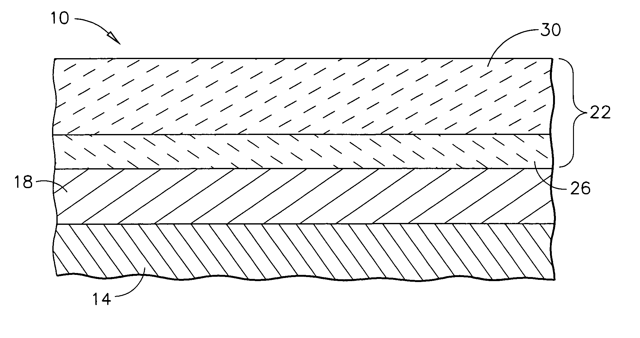
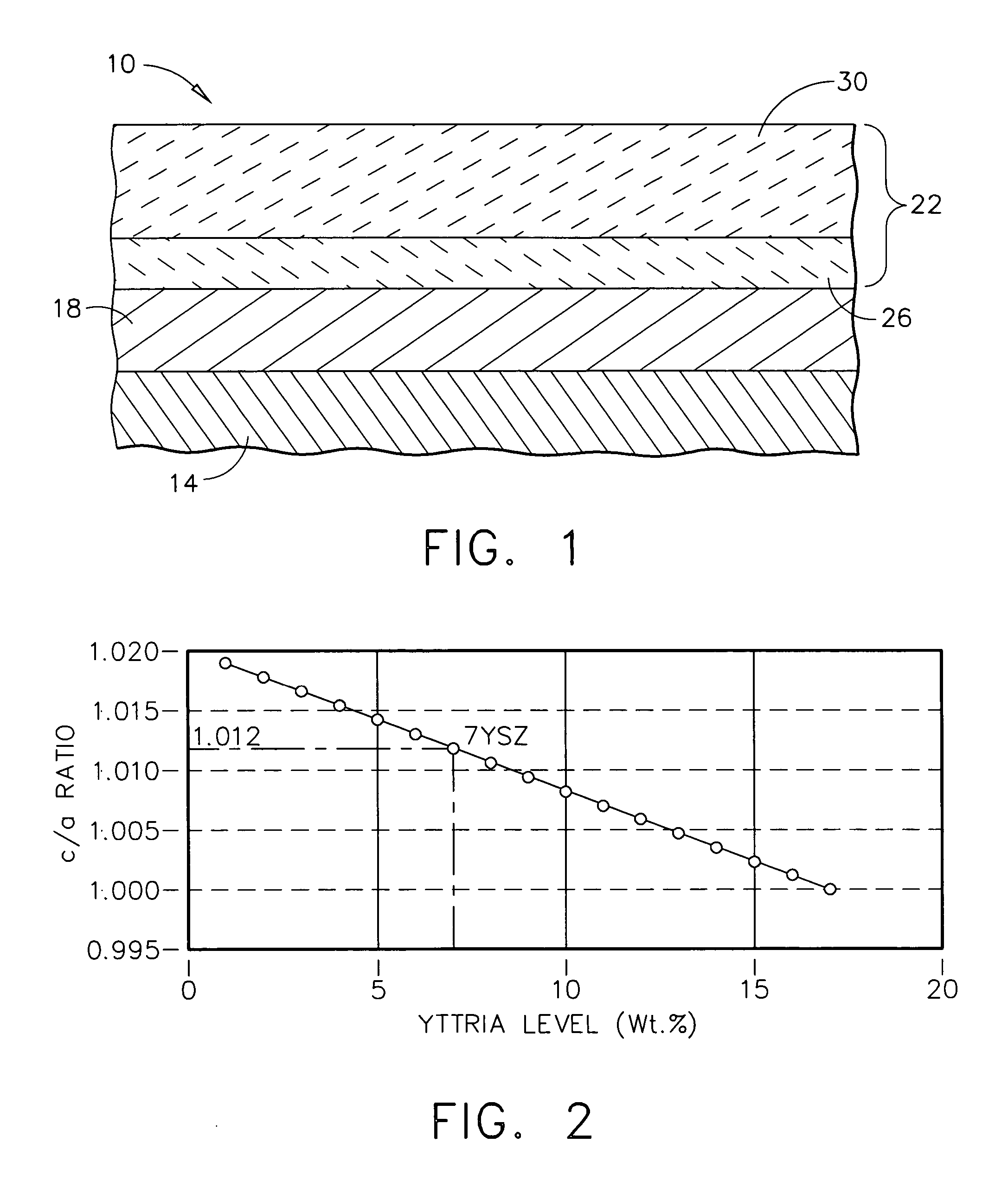
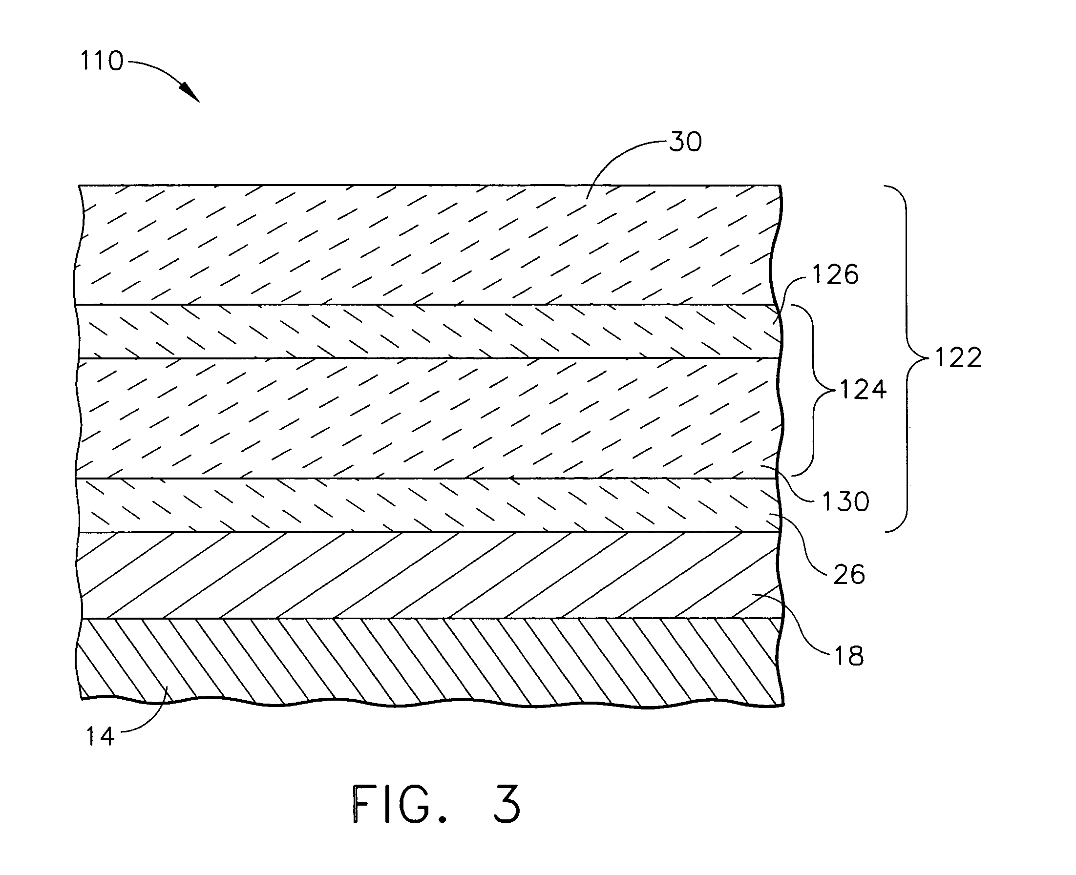
[0022] As used herein, the term “ceramic thermal barrier coating materials” refers to those coating materials that are capable of reducing heat flow to the underlying substrate (e.g., metal substrate) of the article, i.e., forming a thermal barrier, and which have a melting point that is typically at least about 2600° F. (1426° C.), and more typically in the range of from about 3450° to about 4980° F. (from about 1900° to about 2750° C.). Suitable ceramic thermal barrier coating materials for use herein include, aluminum oxide (alumina), i.e., those compounds and compositions comprising Al2O3, including unhydrated and hydrated forms, various zirconias, in particular chemically phase-stabilized zirconias (i.e., various metal oxides such as yttrium oxides blended with zirconia), such as yttria-stabilized zirconias, ceria-stabilized zirconias, calcia-stabilized zirconias, scandia-stabilized zirconias, magnesia-stabilized zirconias, india-stabilized zirconias, ytterbia-stabilized zircon...


PUM

PropertyMeasurementUnit
Lengthaaaaaaaaaa
Fractionaaaaaaaaaa
Fractionaaaaaaaaaa

Abstract

A reduced thermal conductivity thermal barrier coating having improved impact resistance for an underlying substrate of articles that operate at, or are exposed to, high temperatures. This coating comprises an inner high fracture toughness layer nearest to the underlying substrate and having a thickness up to about 5 mils (127 microns) sufficient to impart impact resistance to the thermal barrier coating, and comprises a zirconia-containing ceramic composition having a c/a ratio of the zirconia lattice in the range of from about 1.011 to about 1.016 and stabilized in the tetragonal phase by a stabilizing amount of a stabilizing metal oxide selected from the group consisting of yttria, calcia, ceria, scandia, magnesia, india, lanthana, gadolinia, neodymia, samaria, dysprosia, erbia, ytterbia, europia, praseodymia, and mixtures thereof. The thermal barrier coating further includes an outer thermal insulating layer adjacent to and overlaying the inner layer and comprising a ceramic thermal barrier coating material. The thermal barrier can be used to provide a thermally protected article having a substrate (e.g., metal substrate) and optionally a bond coat layer adjacent to and overlaying the substrate. The thermal barrier coating can be prepared by forming the inner high fracture toughness layer, followed by forming on the inner layer the outer thermal insulating layer.

Description

STATEMENT REGARDING FEDERALLY SPONSORED RESEARCH [0001] This invention was made with Government support under Contract No. N00019-96-C-0176 awarded by the JSF Program Office. The Government may have certain rights to the invention.BACKGROUND OF THE INVENTION [0002] This invention relates to improving the impact and spallation resistance of thermal barrier coatings, especially those coatings having reduced thermal conductivity. This invention further relates to articles having such coatings and methods for preparing such coatings for the article. [0003] Components operating in the gas path environment of gas turbine engines are typically subjected to significant temperature extremes and degradation by oxidizing and corrosive environments. Environmental coatings and especially thermal barrier coatings are an important element in current and future gas turbine engine designs, as well as other articles that are expected to operate at or be exposed to high temperatures, and thus cause th...

Claims


Application Information

Patent Timeline
IPC IPC(8): B32B15/04B32B19/00
CPCC23C14/08C23C28/3215C23C28/3455C23C28/321Y10T428/12611C23C28/345C23C28/42Y10T428/265C23C28/325
Inventor SPITSBERG, IRENEBOUTWELL, BRETT ALLENBRUCE, ROBERT WILLIAM
Owner GENERAL ELECTRIC CO
Why Eureka
Try Eureka